
4541 Timer Relay Circuit 0.3 second to 10 hours

The timing circuit in question operates using two distinct methods for activation, providing flexibility depending on the application requirements. When the START point is connected to ground (GND), the circuit is designed to initiate timing upon receiving a voltage supply. This method is particularly useful in automated systems where grounding can serve as a reliable trigger for the timer.
Alternatively, the use of a switch for activation allows for manual control over the timing process. This approach can be advantageous in scenarios where user intervention is necessary, providing a straightforward means to start the timer on demand. The switch can be a simple toggle or push-button type, which, when engaged, completes the circuit and sends a signal to the timer to commence its operation.
In both configurations, careful attention must be paid to the circuit design to ensure that the timer operates reliably under the intended conditions. Components such as resistors, capacitors, and the timer IC itself must be selected based on the desired timing intervals and the overall voltage levels used in the circuit. Proper layout and grounding practices should also be considered to minimize noise and ensure stable operation.In order to start the timining you have 2 possibilities: you either connect the START point to ground GND and in this case the timer starts when you connect it to the voltage supply or you can place a switch to start it. 🔗 External reference
Related Circuits
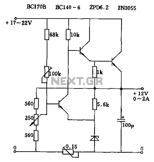
The circuit output voltage can be continuously adjusted from zero to its maximum value. The baseline is established by a constant current sourced from the auxiliary power supply circuit. The reference current of 500 microamperes can be fine-tuned to...
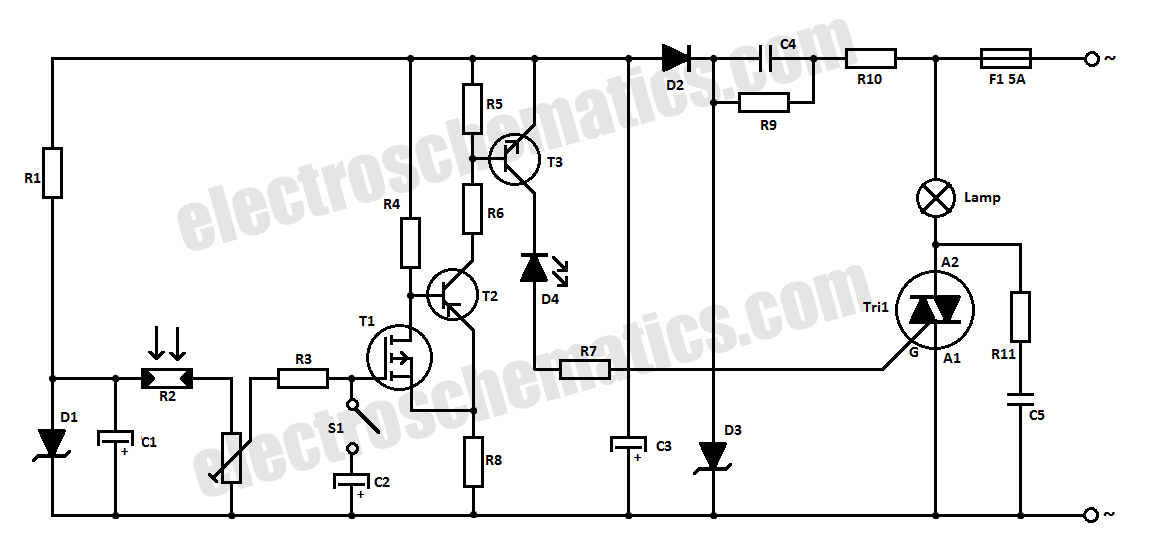
This halogen switch circuit utilizes a FET transistor, as the current is influenced by the gate voltage of the FET. The maximum gate voltage is 12V, making the circuit suitable for 12-volt lamps. The resistor R1 has a value...
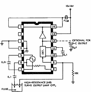
This electronic liquid detector circuit diagram utilizes the ULN2429A monolithic bipolar integrated circuit, which is designed to detect the presence or absence of various types of liquids. The detection mechanism involves comparing the resistance of a probe immersed in...
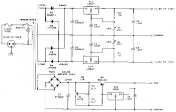
This bench power supply features three solid-state DC power supplies. The first supply provides an output of 1.5 to 15 volts at 1 ampere. The second supply offers a range of -1.5 to -15 volts at 1 ampere. The...
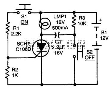
After the SCR is activated, capacitor CI charges up to nearly the full supply voltage through resistor R3 and the anode of the SCR. When switch S2 is later closed, it grounds the positive terminal of CI, causing the...
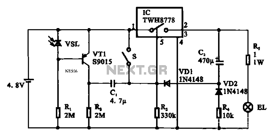
Automatic emergency lamp circuit featuring an electronic switch integrated circuit. This circuit is designed for automatic emergency lighting. The system operates based on ambient light conditions; when light levels are low at night, the circuit activates the emergency lamp....