
Long range FM transmitter

sing the 10K linear potentiometer. The output power of this long range rf transmitter is around 1W but can be higher if you use transistors like KT920A, BLX65, BLY81, 2N3553, 2SC1970, 2SC1971 T1 is used as an oscillator stage to deliver a low power stable frequency. To adjust the freq. use the 10k linear potentiometer like this: if you trim down, towards ground, the freq. will drop and if you adjust it toward + it will rise. Basically the potentiometer is used as a variable power supply for the two BB139 varicap diodes. Those two diodes act like a variable capacitor when you adjust the pot. By varying the diode capacitance the L1 + diodes circuit makes a resonance circuit for T1. You can use transistors like BF199, BF214 but do not use BCs. At this moment you don`t have yet the long range fm transmitter because the power is quite low, no more than 0.
5 mW. T2 and T3 works as a buffer stage, T2 as a voltage amplifier and T3 as a current amp. This buffer stage is very important for freq stabilization because is a tampon circuit between the oscillator and the preamp and final amplifier. It is well known that poor transmitter designs tend to modify freq. as you adjust the final stage. With this T2, T3 stage this won`t happen anymore! T4 is a preamplifier for the fm transmitter and is used as a voltage power rf amplifier and will deliver enough power to the final T5 transistor.
As you can see T4 has a capacitor trimmer in its collector, this is used to make a resonance circuit that will force T4 to amplify better and get rid of those unwanted harmonics. L2 and L3 coils must be at 90 degrees angle one to another, this is to avoid frequency and parasite coupling.
The final stage of the long range rf transmitter is equiped with any rf power transistor that has at least 1 watt output power. Use transistors like 2N3866, 2N4427, 2N3553, BLX65, KT920A, 2N3375, BLY81, 2SC1970 or 2SC1971 if you want to have a pro fm transmitter with enough power to cover a long range area.
If you use 2N2219 you will get no more than 400mW. Use a good heatsink for the T5 transistor as it gets a little hot. Use a good 12V/1Amp minimum stabilized power supply. Start by construction the oscillator stage, solder a small wire to T1 10pF capacitor out and listening to a fm receiver, trim the 10k pot untill you can hear a blank noise or you you plug in an audio source you can hear the music. With a 70cm wire you can cover a 2 3 meter area just with the oscillator stage. Then continue to build the rest of the rf transmitter, use proper shielding as indicated in the circuit schematic.
When you finished the transmitter construction connect the antena or better a 50 or 75 © resistive load and use this rf probe, you can use 1N4148 diode instead of the probe diode. Adjust again the 10k pot to desired freq. and then go to T4 stage and trim the first collector trimmer for maximum voltage indication on the multimeter.
Then continue with the next trimmer and so on. Then go back to the first trimmer and readjust again untill you obtain the highest voltage on the multimeter. For 1 watt rf power you can measure a 12 to 16 Voltage. The formula is P (in watt) is equal to U2 / Z, where Z is 150 for 75 © resistor or 100 for 50 © resistor, but you must remember that the real rf power is lower.
After those adjustment, if everything is going well connect the antenna, continue using the rf probe, readjust again all the trimmers starting from T3. Make sure you don`t have harmonics, check your TV and radio set to see if there is disturbance on the band.
Check this in another room 🔗 External reference
Related Circuits
TR1 (BC547) is an inverted Hartley oscillator which based upon an inductor fabricated on the PCB. This makes it megga-stable, and setable anywhere in the VHF FM band (76MHz to 119MHz) and the BB105 varicap makes it voltage tuneable...
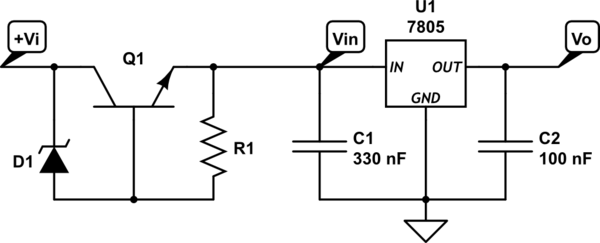
A power supply circuit is designed to convert 24VAC to 5VDC. An L7805CV voltage regulator is used; however, after rectification with a bridge rectifier and smoothing with a 33µF electrolytic capacitor, the input voltage remains at 40V peak, which...
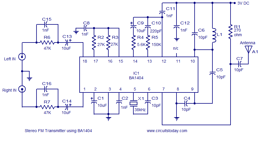
A high-quality stereo FM transmitter circuit is presented. This circuit utilizes the BA1404 integrated circuit from ROHM Semiconductors. The BA1404 is a monolithic FM stereo modulator that incorporates a stereo modulator, FM modulator, and RF amplifier circuitry. The FM...
The current system is a dedicated 486 computer running Homeseer software. The hardware setup includes a CM11A computer-to-X10 interface along with several appliance and lamp modules. Additionally, there is a homebrew infrared (IR) system that connects the computer to...
This is a 6-meter band transmitter RF power amplifier designed for 50 MHz operation, delivering an output power of 100 watts. It is intended for use with the FT-736R transceiver and is driven by a 10-watt signal for 6-meter...
This schematic represents an FM transmitter capable of delivering an output power of 3 to 3.5 W, operating within a frequency range of 90 to 110 MHz. While the stability of the circuit is acceptable, the integration of a...