
Stereo FM transmitter using BA1404

The FM transmitter circuit designed around the BA1404 IC is engineered for high fidelity audio transmission within the FM band, specifically from 76 MHz to 108 MHz. The BA1404's integration of multiple functionalities allows for a compact design while maintaining performance standards. The pre-emphasis network, formed by resistors and capacitors (R7, C16, C14 for the right channel and R6, C15, C13 for the left channel), is critical in enhancing the audio quality by compensating for the inherent frequency response characteristics of FM receivers. This pre-emphasis is vital in reducing noise and distortion, particularly in the higher frequency ranges.
The oscillator circuit, consisting of inductor L1 and capacitor C5, is essential for generating the carrier frequency used in the transmission. The precise tuning of this oscillator ensures that the transmitted signal remains stable and within the desired frequency range. The additional network of capacitors (C9, C10) and resistors (R4, R5) plays a crucial role in improving channel separation, thereby minimizing crosstalk between the left and right audio channels. This is particularly important in stereo transmission, as it ensures a clearer and more distinct listening experience.
The use of a 38 kHz crystal oscillator (X1) connected to the BA1404 enhances the stability of the modulation process. This crystal-controlled frequency allows for accurate generation of the composite stereo signal, which is vital for maintaining sound quality and fidelity during transmission. The overall design of this FM transmitter circuit emphasizes the importance of component selection and configuration in achieving high-quality audio transmission while adhering to the power supply requirements of 1.25 to 3 volts. This adaptability makes the circuit suitable for various applications, including personal audio broadcasting and educational projects.A high quality stereo FM transmitter circuit is shown here. The circuit is based on the IC BA1404 from ROHM Semiconductors. BA1404 is a monolithic FM stereo modulator that has built in stereo modulator, FM modulator, RF amplifier circuitries. The FM modulator can be operated from 76 to 108MHz and power supply for the circuit can be anything betwee
n 1. 25 to 3 volts. In the circuit R7, C16, C14 and R6, C15, C13 forms the pre-emphasis network for the right and left channels respectively. This is done for matching the frequency response of the FM transmitter with the FM receiver. Inductor L1 and capacitor C5 is used to set the oscillator frequency. Network C9, C10, R4, R5 improves the channel separation. 38kHz crystal X1 is connected between pins 5 and 6 of the IC. Composite stereo signal is created by the stereo modulator circuit using the 38kHz quartz controlled frequency.
🔗 External reference
Related Circuits
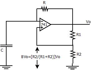
The positive feedback comparator circuit enhances the gain of the operational amplifier (op-amp), facilitating rapid switching between the two states of a multivibrator. This positive feedback also introduces hysteresis into the circuit. A capacitor, denoted as `C`, is connected...
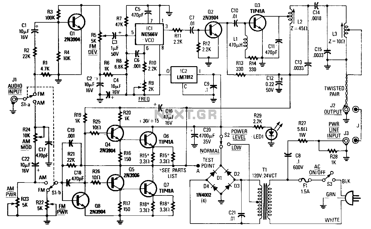
The choice between AM, narrowband FM (less than 15 kHz), or wideband FM (greater than 30 kHz) is determined by the specific application. FM is preferable for music transmission due to its superior noise immunity. For speech or other...
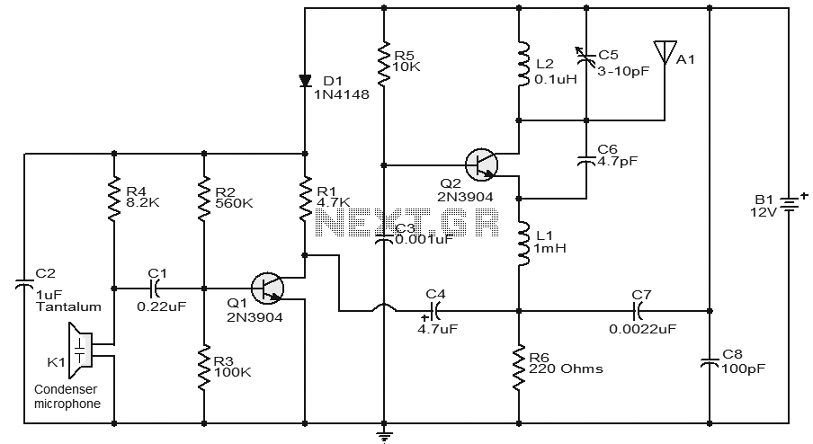
A stable and straightforward FM transmitter circuit is presented here. With a properly matched antenna, this transmitter can achieve a range of approximately 200 meters. The circuit utilizes a condenser microphone (K1) to capture the sound intended for transmission....
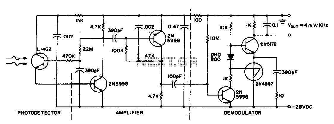
This circuit consists of an L14G2 detector, two stages of gain, and an FM demodulator. Better sensitivity can be obtained using more stages of stabilized gain with automatic gain control (AGC). The circuit design features an L14G2 detector, which serves...
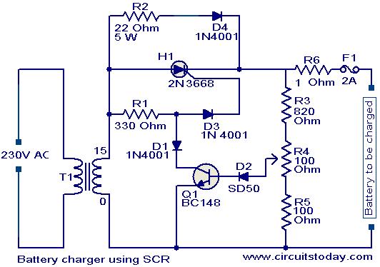
A simple battery charger based on SCR is presented. The SCR rectifies the AC mains voltage to charge the battery. When the battery connected to the charger is discharged, the battery voltage decreases, inhibiting the forward bias voltage from...
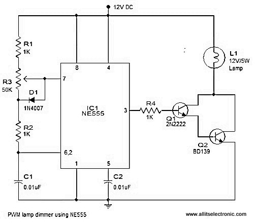
A simple and efficient PWM lamp dimmer utilizing the timer IC NE555 is presented in this article. Traditional linear regulator-based dimmers achieve a maximum efficiency of only 50%, which is significantly lower than PWM-based dimmers that can exceed 90%...