
Loudspeaker Protector Monitors Current Circuit
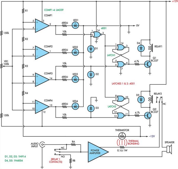
The described circuit employs a set of comparators to monitor voltage levels and activate corresponding indicators and control mechanisms based on the power output of a system, such as an audio amplifier. Each comparator's non-inverting input is connected to a reference voltage, while the inverting input receives the signal from the system. When the monitored voltage surpasses the reference, the comparator output switches high, illuminating an LED as a visual indication of the condition.
The incorporation of NOR gate latches allows for a memory effect in the circuit, enabling the system to maintain the state of the outputs even after the triggering condition has ceased. This is particularly useful in power management applications, where maintaining a specific state (such as disconnecting a loudspeaker) is crucial for preventing damage from excessive power levels.
The attenuation network, consisting of resistors RA and RB, is critical for reducing the power output to acceptable levels. The choice of resistor values is influenced by the characteristics of the thermistor used in the circuit. The thermistor acts as a temperature-sensitive resistor, changing its resistance with temperature fluctuations, which in turn affects the comparator's reference voltage.
The circuit's operation is further enhanced by a setup procedure involving a sine wave oscillator, which serves as a test signal to evaluate the power amplifier's performance. By adjusting trimpot VR1, the user can calibrate the circuit to ensure that the LED indicators function correctly across the expected range of power levels. This design is particularly applicable in audio systems where monitoring and managing output levels are essential for both performance and safety.
Overall, this circuit exemplifies effective voltage monitoring and control, integrating various components to provide a robust solution for managing power levels in electronic systems.When the voltage on the non-inverting input of each comparator exceeds the voltage at its inverting input, the output switches high and illuminates the relevant LED. NOR gate latches are connected to the outputs of the third and fourth comparators. When the third comparator switches high, the first latch is set, turning on Q1 and relay 1. This swi tches in an attenuation network (resistors RA & RB) to reduce the power level. However, if the power level is still excessive, comparator 4 will switch, setting its latch and turning on Q2 and relay 2. This disconnects the loudspeaker load. The thermistor then needs to cool down before normal operation will be restored. The values of R1-R4 depend on the thermistor used. For example, if a thermistor with a resistance of 1. 5kO at 25 °C is used, then R1 could be around 1. 5kO and R2, R3 and R4 would each be 100O (depending the temperature coefficient of the thermistor). The setup procedure involves connecting a sinewave oscillator to the input of the power amplifier and using a dummy load for the output.
Set the power level desired and adjust trimpot VR1 to light LED1. Then increase the power to check that the other LEDs light at satisfactory levels. 🔗 External reference
Related Circuits
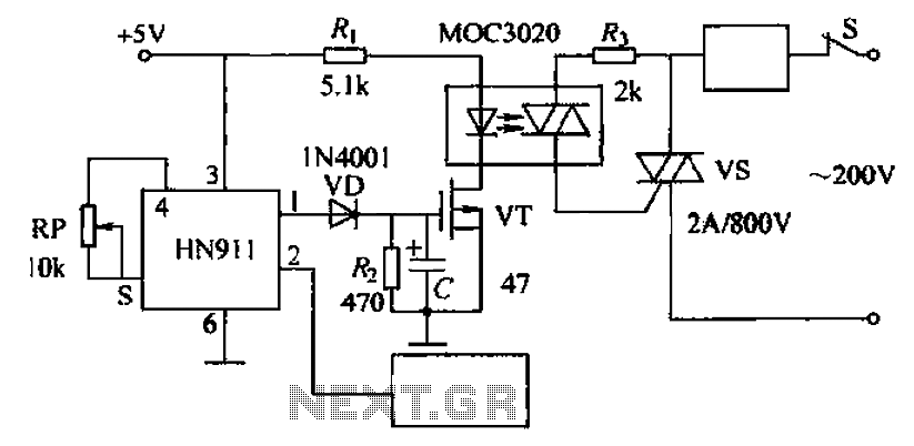
Automatic door control circuit diagram. It utilizes a pyroelectric infrared detection module, HN911, for human motion detection. A variable resistor (potentiometer) is used to adjust the delay time controlled by a transistor (VT). An optocoupler (MX: 3020) provides AC...
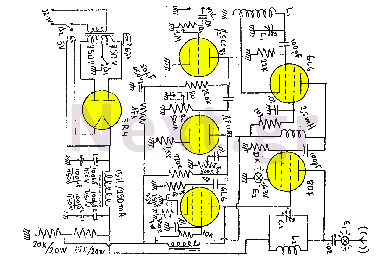
This transmitter consists of a total of five bulbs. The 6L6 tube functions as an oscillator, directing oscillations to the grid of the 807 tube, which serves as the final amplifier and the transmitter output lamp. The amplifier includes...
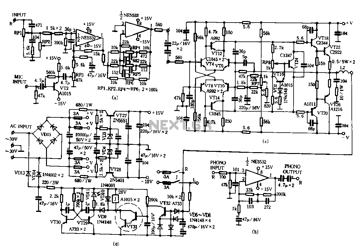
Only the R channel is shown, with the original reference PCB label. Figure (a) illustrates the front tone circuit, which consists of a common negative feedback operational amplifier in an RC circuit configuration. The microphone signal is amplified by...
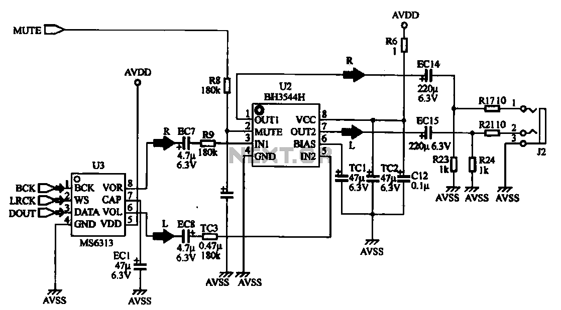
The MP4 audio circuitry consists of audio D/A converters and an audio amplifier combination circuit. This design features a straightforward circuit layout, making it suitable for integration into compact MP4 digital devices. The MP4 audio circuitry is designed to efficiently...
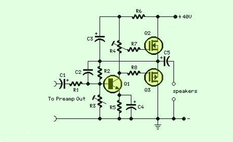
The function of this circuit is an audio amplifier capable of delivering a decent output power with a minimal number of components, with considerable efficiency. This audio amplifier circuit is designed to enhance audio signals, providing sufficient output power while...
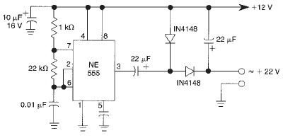
This voltage doubler circuit utilizes a 555 timer integrated circuit configured as an astable multivibrator. It can deliver a maximum output current of 50mA; exceeding this limit will result in a reduction of the output voltage. The actual output...