
Voltage doubler circuit using 555 timer
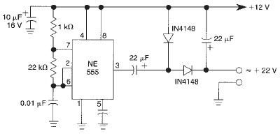
The voltage doubler circuit based on the 555 timer operates by generating a square wave output that is used to charge and discharge capacitors, effectively doubling the input voltage. The 555 timer, when configured as an astable multivibrator, oscillates continuously, creating a pulsed output. This output is then directed to a charge pump configuration, which typically consists of diodes and capacitors.
In this configuration, two diodes are used: one diode allows current to flow during the positive half of the cycle, charging a capacitor to the peak voltage, while the second diode conducts during the negative half, transferring the stored charge to the output capacitor. The capacitors in the circuit must be rated for voltages higher than the expected output to ensure reliability.
The design's limitation to 50mA output current is primarily due to the 555 timer's internal architecture and the characteristics of the passive components used. For applications requiring higher currents, alternative designs or additional stages may be necessary.
It is important to note that the output voltage's stability can be influenced by load variations and component tolerances. To improve performance, filtering capacitors can be added to smooth the output voltage further, and additional regulation may be implemented if a more stable output is required.
Overall, this voltage doubler circuit is suitable for low-power applications where a compact and simple solution is needed to obtain a higher voltage from a lower voltage source.This voltage doubler circuit use a 555 timer integrated circuit wired as an astable mutivibrator. This voltage doubler circuit can deliver only up to 50mA output current and above that current limit the output voltage will be reduced. The actual output voltage will be around 22V for a 12V DC input and also the output voltage will be a bit unstable
. Anyway, for low current applications this circuit is well enough. 🔗 External reference
Related Circuits
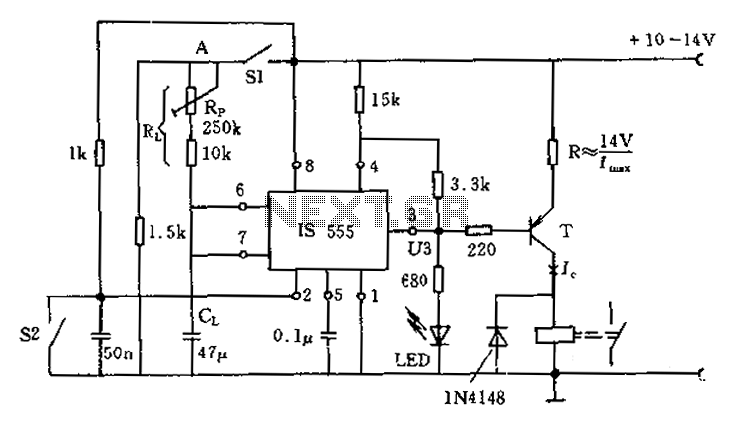
The circuit for the photoelectric switch S1 functions as a control switch for the luggage room light. In its closed operating state, the voltage is positive. If S2 is closed, irrespective of the state of S1, the output terminal...
Upon entering the password, the application, in this case "LED," will illuminate. In this digital locking system project, the interfacing of a keypad and a 16x2 LCD with a microcontroller will be explored, along with the accompanying code. This...
This module utilizes an unconventional topology while retaining the fundamental operational amplifier circuitry of the main module, with some modifications in resistor values. A distinctive feature of this circuit is the incorporation of six-way switches instead of the more...
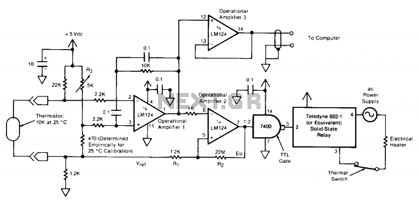
The circuit switches the current to an electrical heater on and off to maintain the temperature of a room at 25 ±0.5°C. The temperature sensor is a thermistor that provides a differential input (for reduced noise) to an operational...
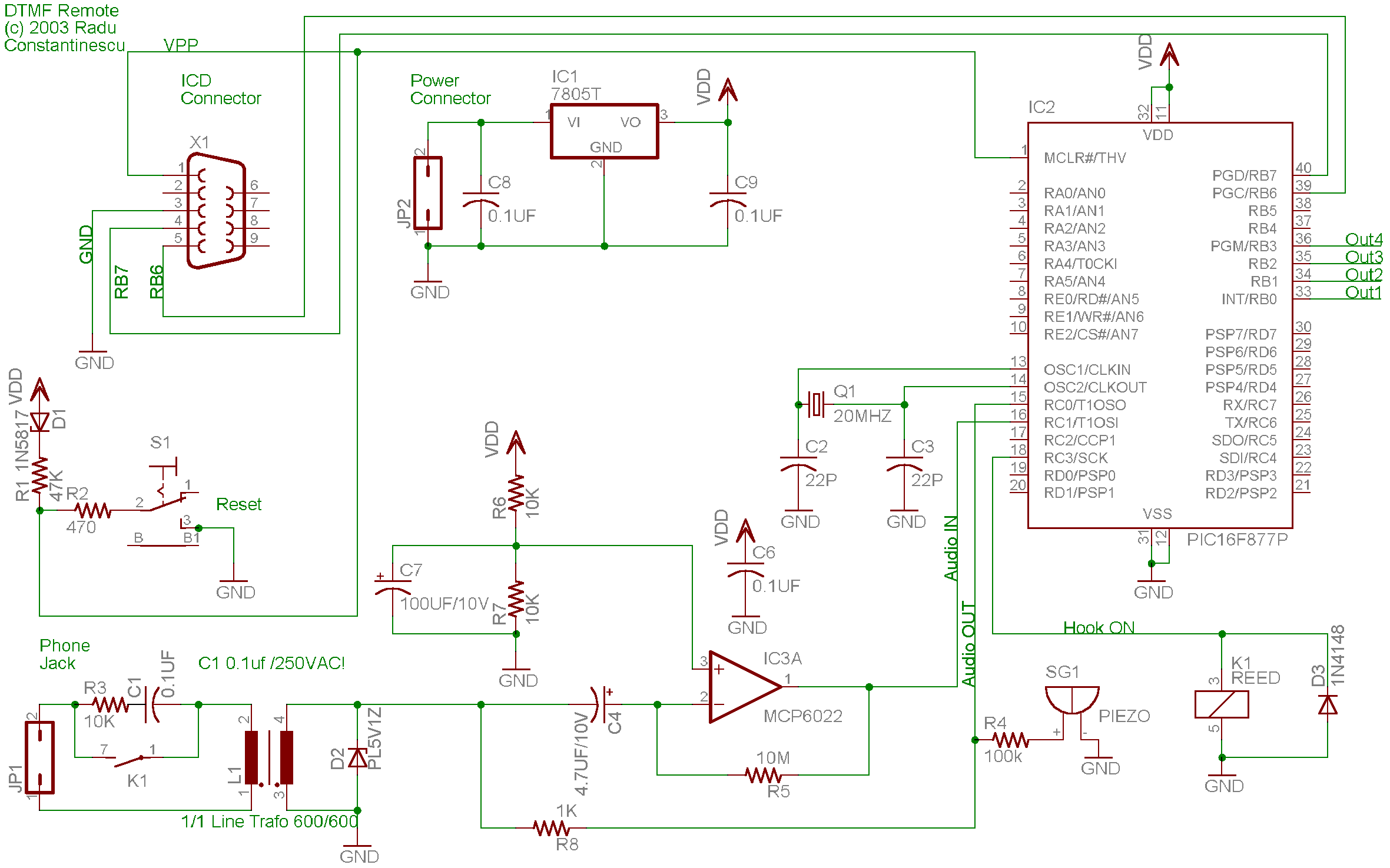
A telephone remote control system allows users to perform various functions remotely using their phone. This system automates complex tasks, simplifying the development and operation of telephone systems. The telephone remote control system is designed to enhance user interaction with...
Chris from PyroElectro.com has an informative article detailing a do-it-yourself radar system constructed using the PIC18F452 microcontroller. This project is an excellent hobbyist endeavor, although the schematic design is quite complex. The system integrates three primary components to form...
Warning: include(partials/cookie-banner.php): Failed to open stream: Permission denied in /var/www/html/nextgr/view-circuit.php on line 713
Warning: include(): Failed opening 'partials/cookie-banner.php' for inclusion (include_path='.:/usr/share/php') in /var/www/html/nextgr/view-circuit.php on line 713