
Low Battery Indicator II

The circuit employs an integrated circuit (IC1) configured as both an oscillator and a comparator to monitor the voltage of a 9V battery. The operation begins with the voltage divider formed by resistors R4 and R5, which generates a reference voltage that is fed into the inverting input of the IC. This reference voltage is crucial for determining the thresholds for battery voltage levels. The non-inverting input of the IC receives the voltage from another voltage divider composed of resistors R1 and R2, which is connected to the battery.
As the battery voltage decreases, the behavior of the LED (LED1) changes according to predefined thresholds. When the battery is fully charged, LED1 emits a steady glow, indicating a healthy battery status. As the voltage falls to around 6.5V, the circuit transitions to a flashing state at a frequency of 5Hz, serving as a warning to the user to prepare a spare battery. If the voltage drops further, to around 5.5V, LED1 turns off completely, signaling that the battery needs replacement.
The timing characteristics of the circuit are governed by capacitor C3, which influences the frequency of the oscillation when the battery voltage is within the operational range. The use of hysteresis, provided by resistor R6, ensures stable operation by preventing rapid toggling of the LED due to minor fluctuations in battery voltage. It is possible to fine-tune the circuit's performance by adjusting the resistor values in the voltage dividers, allowing for customization based on specific battery characteristics or usage requirements.
In summary, this circuit serves as an effective battery life indicator, utilizing an LED to communicate battery status through varying light patterns, thereby providing a straightforward visual cue for battery maintenance.This circuit indicates the remaining battery life bAy varying the duty cycle and flash rate of an LED as the battery voltage decreases. In fact, the circuit actually indicates five battery conditions: (1) a steady glow assures indicates that the battery is healthy; (2) a 2Hz flicker (briefly off) indicates that the battery is starting to show age;
(3) a 5Hz 50% duty-cycle flash is a warning that you should have a spare battery on hand; (4) a brief flicker on at a 2Hz rate indicates the battery`s last gasp; and (5) when the LED is continuously off, it`s time to replace the battery. IC1 is wired as an oscillator/comparator, with a nominal fixed voltage reference of about 1. 5V on its pin 2 (inverting) input (actually, it varies between about 1. 7V and 1. 4V depending on the hysteresis provided via R6). This reference voltage is derived from a voltage divider consisting of resistors R4 & R5, which are connected across the 5V rail derived from regulator REG1, and feedback resistor R6.
Similarly, IC1`s pin 3 input (non-inverting) is connected to a voltage divider consisting of R1 & R2 which are across the 9V battery. Using the component values shown, the circuit will switch LED1 from being continuously on to flash mode when the 9V battery drops to about 6.
5V. Subsequently, LED1 is continuously off for battery voltages below 5. 5V. Naturally, you can tweak the resistor values in the divider network for different voltage thresholds as desired. In operation, the circuit oscillates only when the sampled battery voltage (ie, the voltage on pin 3) is between the upper and lower voltage thresholds set on pin 2.
Capacitor C3 provides the timing. Above and below these limits, IC1 simply functions as a comparator and holds LED1 continuously on or off. Finally, to precisely set the "dead-battery" threshold, make R4 adjustable to offset the variations in regulator tolerance.
🔗 External reference
Related Circuits
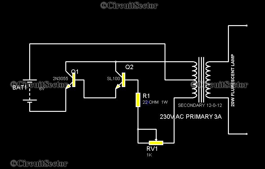
This is a straightforward circuit for an emergency light that can be assembled with relative ease. The components include two transistors, a transformer, a 20 Watt fluorescent tube, a 6V battery, and several resistors and potentiometers. The transformer in...
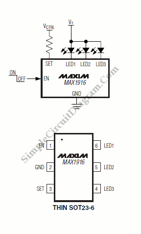
In conventional white LED design, the Max1916 low-dropout bias supply for white LEDs serves as a high-performance alternative to simple ballast resistors. The Max1916 is an integrated circuit designed to provide a stable and efficient bias supply for white LEDs....
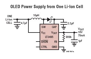
The LT3495, LT3495B, LT3495-1, and LT3495B-1 are low-noise boost converters equipped with an integrated power switch, feedback resistor, and output disconnect circuitry. These devices manage power delivery by adjusting both the peak inductor current and the switch off-time, resulting...
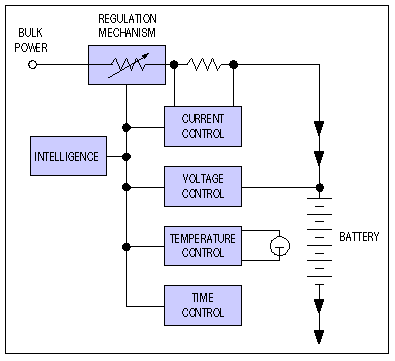
Application note on designing linear and switch-mode (switching DC-DC converter current source) battery charger applications that require external microcontrollers and related system-level issues for notebook computers. The application note provides guidance on the design of both linear and switching DC-DC...
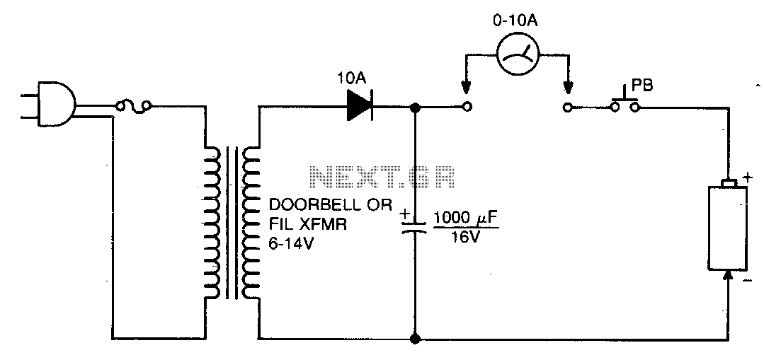
This circuit is designed to eliminate internal shorts in nickel-cadmium batteries. To operate, connect the nickel-cadmium battery to the output and press the pushbutton for three seconds. The circuit functions by utilizing a controlled discharge process to clear internal shorts...
This simple low voltage tester circuit can be used to monitor batteries and other voltage sources for issues, utilizing an LED display and alarm sound. The low voltage tester circuit is designed to provide a reliable method for monitoring the...