
Simple ni-cad battery zapper
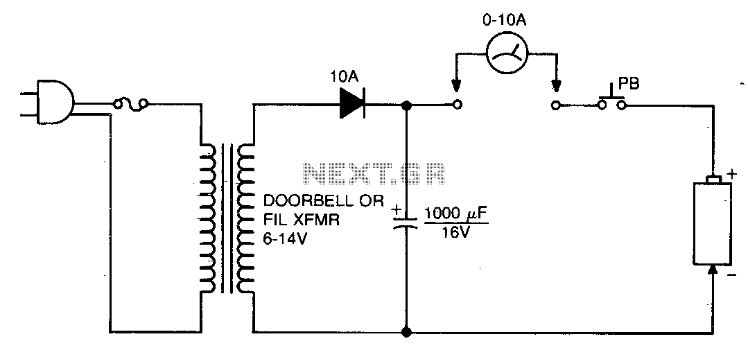
The circuit functions by utilizing a controlled discharge process to clear internal shorts within the battery cells. It typically includes a power source, a pushbutton switch, and output terminals for connecting the battery. The pushbutton initiates the discharge cycle, allowing a brief but controlled flow of current through the battery. This action can help to break down the short circuit within the cells, potentially restoring functionality to the battery.
Key components may include a resistor to limit the current during discharge, ensuring that the process does not damage the battery. A diode might be included to prevent reverse current flow, protecting the circuit from potential damage. Additionally, a capacitor can be employed to smooth the discharge current, providing a more stable output.
The circuit should be designed with safety features, such as an indicator LED to show when the discharge process is active. Proper thermal management should also be considered, as excessive heat can damage the battery or the circuit components. It is crucial to follow manufacturer specifications for the specific battery type to avoid over-discharging, which can lead to permanent damage.
Overall, this circuit serves as a practical solution for maintaining nickel-cadmium batteries, ensuring they remain operational and extending their lifespan through effective management of internal shorts.This circuit is used to clear internal shorts in nickel cadmium batteries To operate, connect ni-cad to output and press the pushbutton for three seconds. 🔗 External reference
Related Circuits
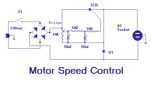
This circuit will allow you to control the speed of an AC motor, for example an electric drill. The way that this circuit works is as follows. The bridge rectifier produces dc voltage from the 120vac line. A portion...
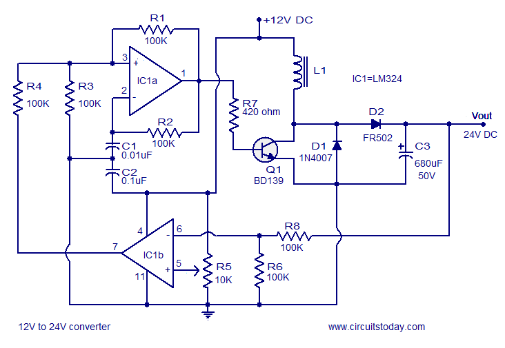
A simple 12V to 24V DC-DC converter circuit diagram built around the LM324. This boost converter schematic can provide up to 800mA output current and a steady 24V DC. The described circuit utilizes the LM324 operational amplifier as the core...
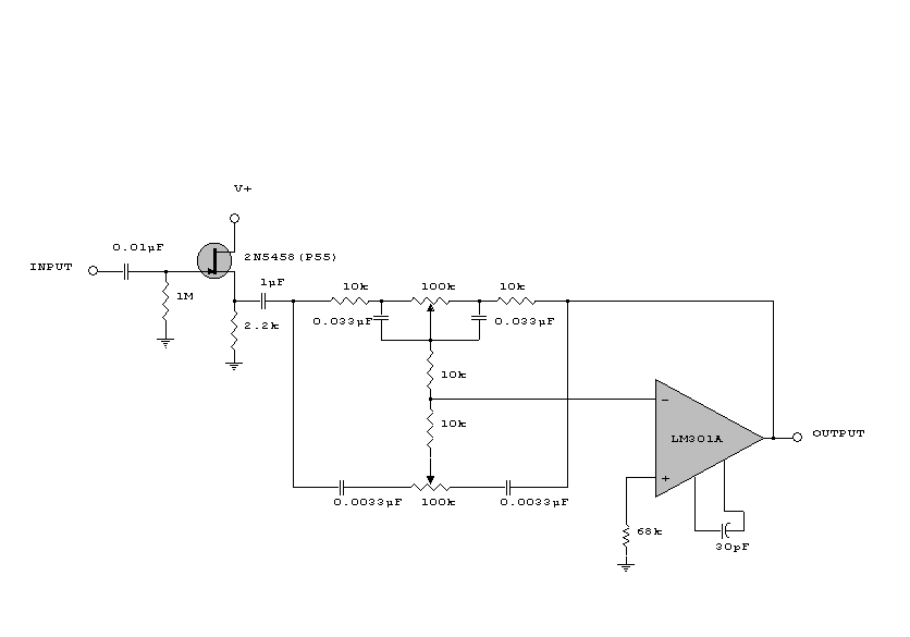
This circuit is a simple series tone control circuit. It utilizes the surgical amplifier LM301A. The JFET 2N3684 provides high input impedance and low noise for the unbuffered operational amplifier, which operates in an equalizer (EQ) configuration. Further details...
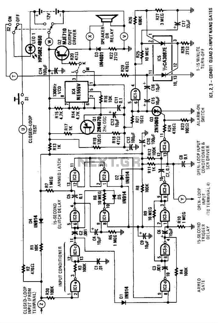
This house alarm circuit features both open and closed loop sensors and includes a self-shutdown function. The delay after triggering can be adjusted between 1 minute and 12 minutes, while the delay before triggering is set at 13 seconds....
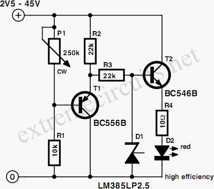
This circuit provides a straightforward method for measuring the voltage of a low-impedance voltage source. It operates as follows: P1, a 1-W potentiometer, acts as a voltage divider in conjunction with resistor R1. The voltage at their junction is...
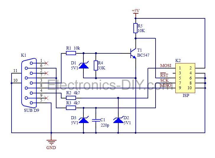
This is a simple AVR programmer designed for Atmel microcontrollers from the AVR family that support serial programming. The programmer connects to a PC via the RS232 serial interface and is compatible with PonyProg or Avrdude software. It is...