
Low Cost Amplifier Circuit Using Three Transistors

The low-cost amplifier circuit employs two types of transistors, BC107 and BC148, which are commonly used for their favorable characteristics in audio amplification applications. The BC107 is a general-purpose NPN transistor, while the BC148 is also an NPN transistor with slightly higher voltage ratings, making them suitable for various amplification tasks.
The circuit typically consists of a common-emitter configuration, where the input signal is applied to the base of the first transistor (BC107). This transistor amplifies the input signal, and the output is taken from its collector. The amplified signal is then fed into the base of the second transistor (BC148), which further amplifies the signal. The output from the collector of the BC148 provides a higher power version of the input signal.
Biasing resistors are essential in this circuit to ensure that both transistors operate in the active region. The resistors set the base current, allowing for proper operation without distortion. Capacitors may also be included to couple the input and output signals while blocking any DC components, ensuring that only the AC signal is amplified.
The power supply for the circuit typically ranges from 9V to 12V, which is adequate for the operation of both transistors. A bypass capacitor may also be used across the emitter resistor to enhance the gain at higher frequencies.
This low-cost amplifier circuit is particularly beneficial for applications where budget constraints exist, yet reliable audio amplification is required. The simplicity of the design, along with the availability of the components, makes it an excellent choice for hobbyists and educational purposes in electronics.The working and circuit diagram of a low cost amplifier using transistors BC107, and BC148 is explained in detail.. 🔗 External reference
Related Circuits
This circuit offers an advantage over traditional continuity testing devices, which typically utilize a multimeter to assess circuit continuity. Multimeters are not suitable for testing high impedance or resistance circuits, such as transformers, capacitors, and high-value resistors. This circuit...
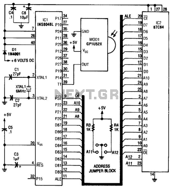
This circuit is based on the Sharp GP1U52X infrared module and the 1NS8048L microprocessor. The GP1U52X is a hybrid integrated circuit and infrared detector that provides a strong, clean signal for subsequent filtering and demodulation. The circuit utilizes the Sharp...
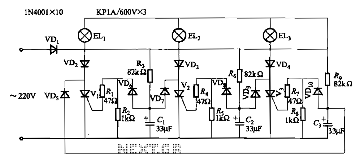
The circuit operates with a 220V mains supply through a diode (VDi) configured as a half-wave rectifier. Capacitors C1 to C3 are charged, and due to the lack of full synchronization in the charging process, a pilot thyristor is...

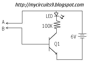
The diagram illustrates the principle circuit of a radio control car receiver. Important notes include the selection of transistor Q1, which is specified as either 1815 or 9018, along with the bias resistor R1, which has values of 240K...
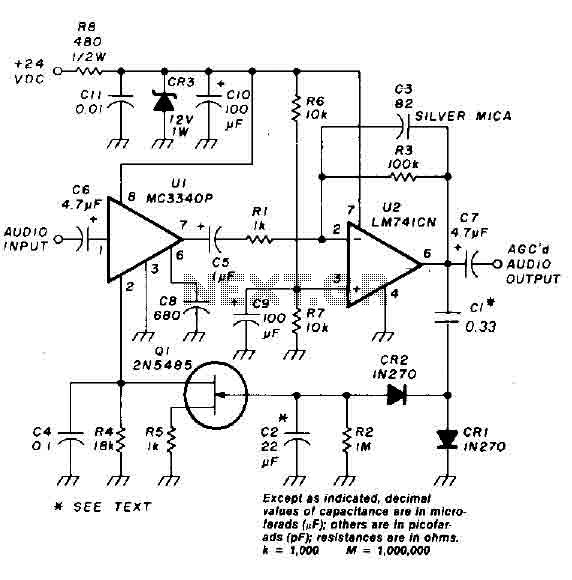
An audio signal applied to the input VI is passed through the operational amplifier 741, designated as U2. After amplification, the output signal V2 is sampled and sent to a negative voltage doubler/rectifier circuit composed of diodes CR1 and...
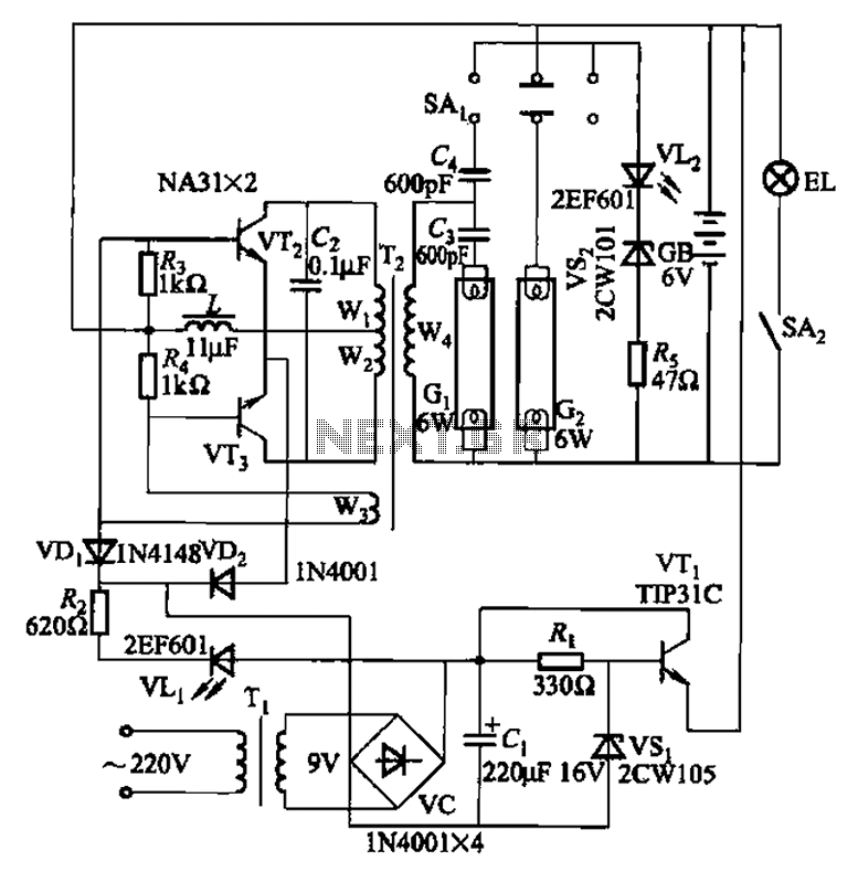
This is a Nissan Panasonic rechargeable emergency fluorescent lamp circuit. It features built-in 6V, 4Ah high-energy batteries that can be directly charged. The circuit supports two 6W fluorescent lamps. It includes functional switches SAi and SAz. When SAi is...