
Auto gain control op-amp circuit
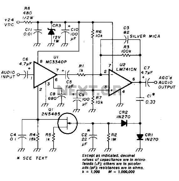
As the voltage applied to the gate of the FET becomes more negative in magnitude, the channel resistance of the FET increases, causing it to operate as a voltage-controlled resistor. The MC3340P audio attenuator is the core component of the system, capable of providing 13 dB of gain or nearly -80 dB of attenuation, depending on the external resistor placed between pin 2 and ground. An increase in this resistance results in a decrease in gain from the MC3340P. The gain of the circuit is not a perfectly linear function of the external resistance, but it exhibits similar behavior across much of the gain/attenuation range. An input signal applied to the Automatic Gain Control (AGC) will cause the gate voltage of the FET to become negative, leading to an increase in the resistance from pin 2 to ground of the MC3340P, thereby reducing the gain. This mechanism helps to maintain a relatively constant AGC output.
The circuit employs an operational amplifier (U2) to amplify the incoming audio signal, which is critical for ensuring that the signal is strong enough to be processed by subsequent stages. The negative voltage doubler/rectifier circuit, formed by diodes CR1 and CR2 along with capacitor C1, converts the amplified audio signal into a usable negative voltage that controls the FET (Q1). The FET's operation as a voltage-controlled resistor allows for dynamic adjustment of the signal path, effectively modulating the audio signal based on the control voltage derived from the rectified output.
The MC3340P is designed to provide a wide range of gain control, making it suitable for applications requiring precise audio signal manipulation. The external resistor connected to pin 2 plays a vital role in setting the gain or attenuation level, allowing for fine-tuning based on specific application requirements. The overall behavior of the circuit, particularly in relation to the AGC function, ensures that variations in input signal levels do not result in significant fluctuations in output levels, thereby enhancing the stability and performance of the audio processing system.An audio signal applied to VI is passed through the operational amplifier 741, U2. After being amplified, the output signal V2 is sampled and applied to a negative voltage doubler / rectifier circuit composed of diodes CRI and CR2, with the capacitor C1. The resulting negative voltage is used as a control voltage which is applied to the door] 2N5485 FET Q1.
Capacitor C2 and resistor R2 form a filter for smoothing the voltage rectified audio control. The lFET is connected between pin 2 of the MC3340P grounded by a resistor of 1 kohm.. As the voltage applied to the gate of FET] becomes more negative in magnitude, the channel resistance of FET] increases causing lFET to function as a voltage-controlled resistor. The MC3340P audio attenuator is the heart of the MCO. It is capable of 13 dB of gain or almost - 80 dB of attenuation as a function of external resistor placed between Pin 2 and ground.
An increase in resistance decreases the gain from the MC3340P. The gain of the circuit is not entirely a linear function of the external resistance, but such behavior is similar across much of the gain / attenuation range. An input signal applied to the input of the AGC will cause the gate volt age the proportion lFET become negative.
Accordingly, the JFET increases the resistance of the pin 2 to ground the MC3340P causing a reduction in gain. In this way, the AGC output is kept almost constant. 🔗 External reference
Related Circuits
The MP3 files (up to 65,536) are stored on a micro SD card. This embedded MP3 module is a universal and compact circuit (37 mm x 27 mm) designed for playing MP3 audio files. The MP3 module can be...
Using only a single transistor and a few passive components, a fairly sensitive peak detector circuit can be built. This peak detector circuit is suitable for various applications. The peak detector circuit utilizes a single transistor, typically configured in a...
This compact device, designed primarily for modelers, provides instantaneous readings of pulse duration in milliseconds (ms). It can measure servomotor positions, typically ranging from 1 ms to 2 ms, and can also perform repetitive or non-pulsed measurements, such as...
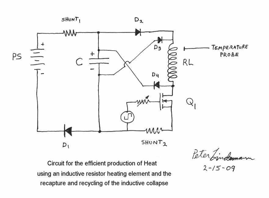
Rosemary's original test circuit is shown in the article she tried to have published in a refereed scientific journal, but the submission was always rejected. In the last 5 months, I have had extensive email correspondence, and numerous telephone...
A voltage supply ranging from 6 V to 15 V is required when using a single LED per module. An increase in the number of LEDs necessitates a corresponding increase in the voltage supply, with additional LEDs connected in...

The term "pentester" refers to a penetration tester, individuals who assess security vulnerabilities. Many high-end hotels globally depend on keycard locks for securing hotel rooms. However, recent incidents of theft have shown that these locks may not be as...