
Low Cost Automatic LED Emergency Light

The emergency light circuit using a white LED is designed for efficiency and cost-effectiveness. The core component, the LM317 integrated circuit, serves as a voltage regulator that ensures the LED receives a stable voltage for optimal performance. The circuit typically operates from a transformer that converts the mains voltage to a lower AC voltage, which is then rectified to DC using a diode bridge.
The LM317 requires a minimum input-output voltage difference to function correctly, making it suitable for applications where the input voltage can vary. The output voltage can be adjusted using a variable resistor (potentiometer) connected to the adjustment pin of the LM317, allowing for fine-tuning of the LED brightness.
The resistor in the circuit is essential for current limiting, preventing the LED from drawing excessive current that could lead to overheating and failure. The value of the resistor is chosen based on the LED specifications and the desired current flow.
In summary, this low-cost emergency light circuit is efficient, utilizing commonly available components to provide reliable illumination during power outages or emergencies. The design emphasizes simplicity and functionality, making it an excellent choice for DIY enthusiasts and practical applications.This is a low cost circuit diagram for the emergency light based on white LED. Component: LM317 IC, Resistor, Transformer, LED, Variable .. 🔗 External reference
Related Circuits

For this LED driver electronic project, a DC power supply circuit is required to provide an output voltage between 2.7V and 5.5V. The supply voltage must be applied between Vin and GND. The T/F jumper connects the T post...

This is a low-cost and simple intercom circuit design. Some intercom circuits are built using integrated circuits. The circuit described here utilizes three readily available transistors that can be easily found in electronic stores. Even a novice can assemble...
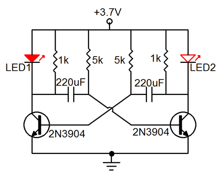
Many friends have requested an automatic on/off LED circuit or an LED flashing circuit. This post presents an astable multivibrator circuit designed for LED flashing. It is a simple astable multivibrator circuit utilizing two LEDs (specifically red LEDs) and...

Often, for various reasons, individuals forget or are unable to water the plants in their homes. Many humidity sensor units merely alert users with a beeping sound or a flashing light when the pot requires watering. However, what if...

A light dimmer circuit is used to adjust the illumination of a lamp. The following circuit illustrates a basic TRIAC triggering circuit that utilizes a DIAC. In this circuit, the illumination of the light is regulated through the interaction...

This low-cost burglar alarm utilizes a 12V strobe light and a truck reversing horn as the visible and audible outputs, respectively, while the alarm system operates on a 12V power supply. The burglar alarm circuit is designed to provide an...