
Astable multivibrator-2 LED flashing circuit2N39043.7V
The astable multivibrator circuit operates continuously between its two unstable states, producing a square wave output that can drive the LEDs to flash alternately. The core of the circuit consists of two NPN transistors configured in a feedback loop. When one transistor turns on, it allows current to flow through the corresponding LED, causing it to illuminate. This action simultaneously turns off the other transistor, resulting in the second LED being off. The timing of the flashing is determined by the values of the resistors and capacitors connected to the transistors.
For this circuit, the recommended configuration includes two resistors (R1 and R2) and one capacitor (C1). The resistor values can be adjusted to control the frequency of the flashing LEDs. A common choice for R1 and R2 may be in the range of 1kΩ to 10kΩ, while C1 can be selected based on the desired timing, typically in the range of 10µF to 100µF. The circuit can be powered by a compact power source, such as a lithium-ion battery from a mobile phone, providing a voltage of +3.7V, which is optimal for the operation of the 2N3904 transistors.
In summary, this astable multivibrator circuit is an effective solution for creating a simple LED flashing effect. The use of readily available components such as the 2N3904 transistors and standard resistors and capacitors makes the circuit easy to assemble and modify for various applications. Adjusting the component values allows for customization of the flashing frequency and brightness of the LEDs, making it a versatile choice for hobbyists and engineers alike.Many of my friends asked me for automatic on off led circuit or led flashing circuit so here I`m going to post a Astable multivibrator-2 LED flashing circuit. It is a simple astable multivibrator circuit using 2LED (here i used red LED), two NPN small transistor 2N3904 for switching.
Here other small NPN transistor can be used, including 2N4401, 2 N2222 or PN2222. Supply voltage is +3. 7V to +5V or if you want to supply a larger volt then add a required resistor series connected with 2 LED`s. I recommend to use +3. 7V for best result. for +3. 7V you can use a battery of mobile phone. 🔗 External reference
Related Circuits
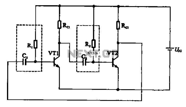
An astable multivibrator is constructed using multiple electronic components and is commonly utilized in pulse signal generation circuits. It operates as depicted in Figure 17-18. The configuration involves two transistors, VT1 and VT2, coupled to capacitor C2 and resistor...
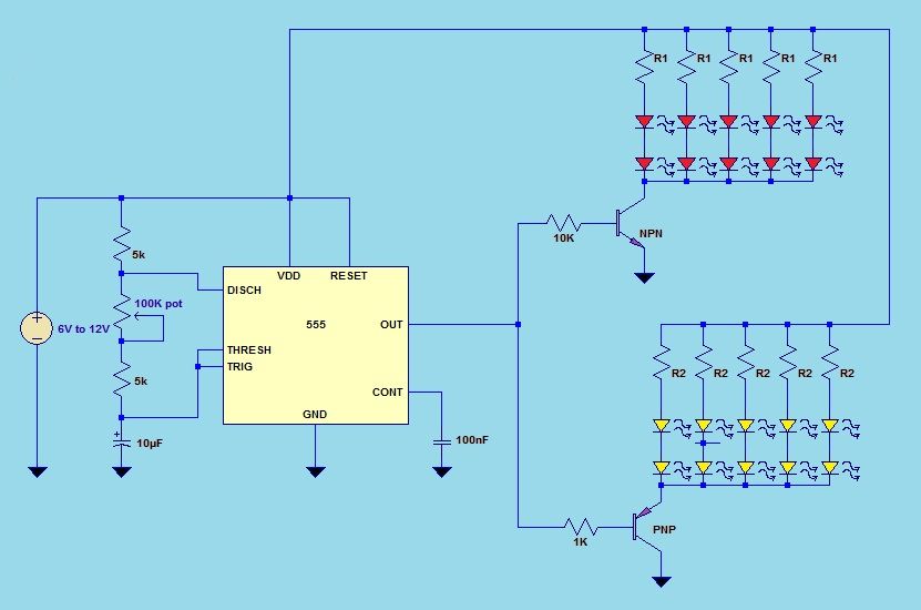
This project utilizes a 555 timer integrated circuit (IC) in an 8-pin configuration to control multiple LEDs. It is designed for quick assembly and allows for the adjustment of timing functions. The circuit employs a 555 timer in astable mode,...
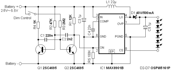
The circuit illuminates a high-brightness LED even at a voltage of 0.8V if the battery can supply 93mA at this voltage. The average step-up efficiency from 0.8V to 1.5V is 75%, with a peak efficiency of 83% occurring around...
This was designed to flash a pair of LEDs to be mounted on the wing tips of a Parkzone Citabria R/C (remote control) airplane. The unmodified Parkzone Citabria only weighs 20 grams (about 0.7 oz), so weight, and therefore...

Note first the battery to be treated at the center of the figure. It is connected to contacts of a relay. The diagram shows the relay at rest. Under these conditions the battery is in SHOCK. His pole -...

The VCO is based on a Hartley oscillator. The frequency is determined by L1 and capacitor C1. The tuning voltage will change the capacitance in the varactor BB132 which will change the oscillation frequency. The value of capacitor C2...
Warning: include(partials/cookie-banner.php): Failed to open stream: Permission denied in /var/www/html/nextgr/view-circuit.php on line 713
Warning: include(): Failed opening 'partials/cookie-banner.php' for inclusion (include_path='.:/usr/share/php') in /var/www/html/nextgr/view-circuit.php on line 713