
Low cost Mic Mixer
For the proposed application involving two 3.5mm microphone jacks connected to headsets, the circuit can be adapted to function effectively. Each microphone jack can be connected to the input channels of the mixer, allowing for simultaneous audio input from both microphones. The output from the mixer can then be wired to the headsets, enabling communication between the driver and navigator.
To enhance usability, it is recommended to incorporate potentiometers at each headset output. This will allow for individual volume control, catering to the preferences of each user. The circuit can indeed be powered directly from a 12V supply, provided that the selected components are rated for this voltage. Care must be taken to ensure that the chosen PNP transistor can handle the required current and voltage levels without distortion or overheating.
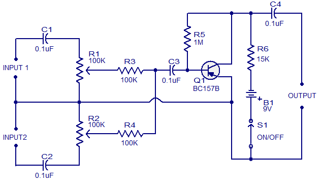
Overall, this circuit design offers a practical solution for creating a cost-effective intercom system using readily available components, making it suitable for extended use in situations requiring continuous communication.This is the schematics of a low cost mic mixer that can be assembled from the components in your junk box. This two channel mike mixer is designed for handling high impedance dynamic microphones. Transistor Q1 can be any general purpose pnp transistor like BC177 or BC157B. Resistor R5 biases the transistor while R3 and R4 provides channel isolation. How ever better the transistor quality better the performance. C1 and C2 performs the job of input coupling and DC isolation while C4 is the output DC decoupling capacitor. Resistors R1 and R2 can be used for the level control of input signals. Avoid using power transistors for Q1. This is because power transistors have high leakage current and it adds to the noise which is not suitable for our purpose here I am an entrant in a 12 day 6, 500 km car rally through Europe.
The organisers have recommended that we use an intercom between driver and navigator as we will need to be talking to each other almost continuously for ten hours a day whilst map-reading and driving. Professional systems are available for close to $1, 000 but I feel that I should be able to get away with a couple of PC headsets and an appropriate amp.
That said, I am a mechanical engineer and so am out of my depth on this website! Would this circuit work with the two 3. 5mm microphone jacks plugged in as the microphones and the output simply wired to the two headsets If so, and given that I have no junk box, what would be the best transistor Could I put a pot on each headset output to control volume Would it work wired directly to 12V 🔗 External reference
Related Circuits
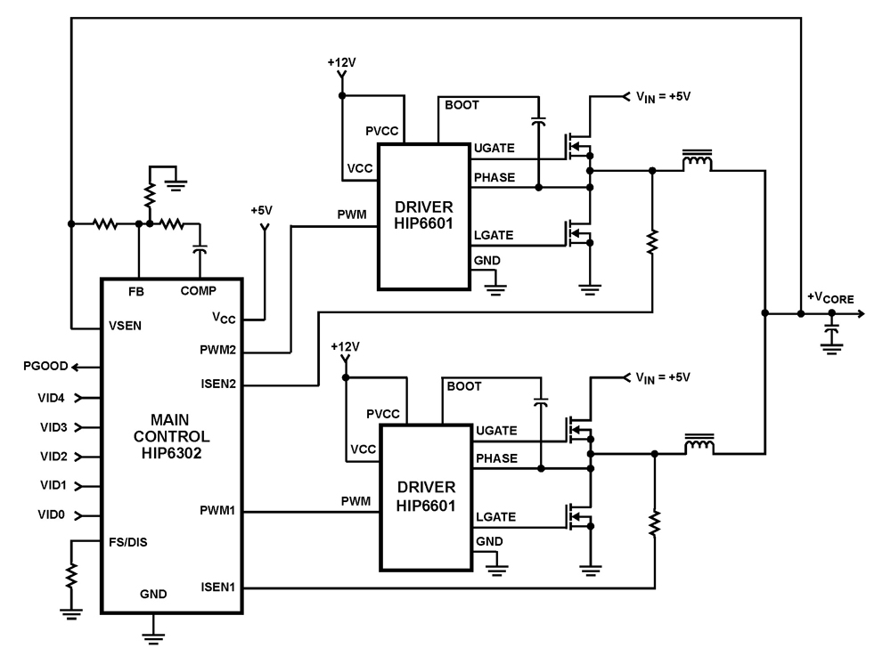
The HIP6302 Multiphase PWM control IC, along with its companion gate drivers (HIP6601, HIP6602, or HIP6603) and Intersil MOSFETs, delivers a precise voltage regulation system for advanced microprocessors. Multiphase power conversion represents a significant advancement over traditional single-phase converter...
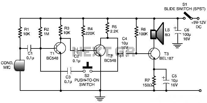
This is a low-cost and simple intercom circuit design. Some intercom circuits are built using integrated circuits. The circuit described here utilizes three readily available transistors that can be easily found in electronic stores. Even a novice can assemble...
This design features a straightforward configuration that is effective and cost-efficient to construct. It consists of six independent microphone amplifiers capable of providing up to 60dB gain (theoretical, not tested). Each channel is equipped with its own fader and...
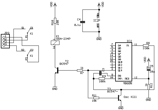
A simple program that will blink an LED. All that is required is a basic JDM programmer, and the setup is ready to go. The circuit requires a power supply, and while a good power generator is recommended, a...

The circuit operates as a unijunction transistor relaxation oscillator. The base of the lower PNP transistor is biased at approximately half of the supply voltage. As the 100pF capacitor charges through the 1GΩ resistor, the base of the upper...

The value of capacitor C2 can be selected to achieve the desired level of smoothness, as its capacitance is effectively amplified by the combined gains of transistors Q1 and Q2. For instance, if a capacitance of 100 µF is...