
A Beginners Guide to Microchip PIC Microcontroller Programming

A schematic for this LED blinking circuit involves several key components. The primary component is the PIC microcontroller, which is programmed to control the LED's state. The microcontroller should be connected to a power supply circuit, which can consist of a transformer that steps down the voltage from an AC source to a suitable DC voltage for the microcontroller, typically 5V.
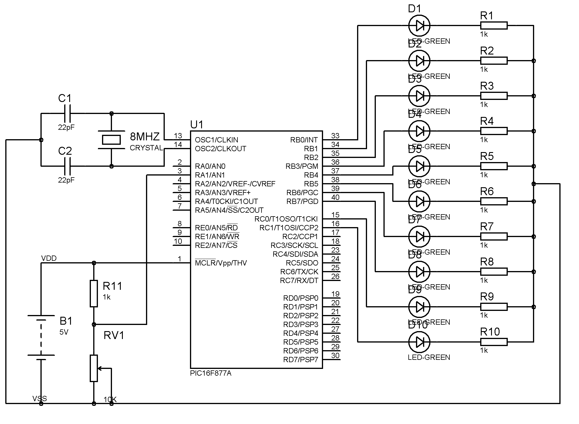
The TRISC register must be configured to set the PORTC pins as outputs. This is accomplished through a series of digital connections from the microcontroller to the LED. The anode of the LED connects to one of the PORTC pins, while the cathode connects to ground through a current-limiting resistor, typically around 220 ohms to 1k ohm, to prevent excessive current from damaging the LED.
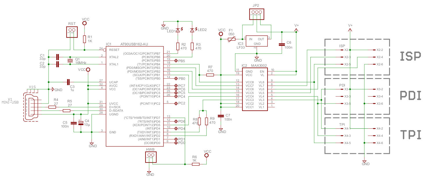
The serial cable connection to the COM port facilitates programming the microcontroller. The ICSP header on the PIC programmer connects to the appropriate pins on the breadboard, allowing for in-circuit programming. The schematic should also include decoupling capacitors near the power supply pins of the microcontroller to filter out noise and stabilize the power supply.
The control logic for the LED blinking is implemented in software, where the PORTC register is manipulated to turn the LED on and off in a loop, creating a visual blinking effect. The timing of the blinking can be adjusted by modifying the delay mechanism within the loop, although it is noted that the current implementation may not be the most efficient method for generating delays.
In summary, this simple LED blinking circuit provides a practical introduction to microcontroller programming, circuit design, and the use of basic electronic components, while illustrating the fundamental principles of digital output control.A simple program that will blink a LED. All you need is a simple JDM programmer (read on for detials), and you are good to go! Our circuit needs power supply. A good Power generator is recomanded, but if you don`t have one and don`t want to buy one, you can use a simple transformator Connect the transformator to your circuit and turn the switch on. the green led should turn on. Connect a serial cable from you com port to the PIC programmer, and then connect the PIC programmer ICSP header to the breadboard using the right connector. Set the TRISC register. The TRISC register is an 8 bit register which sets the states of the PORTC pins of the PIC. A pin state can either be 0, which means an output, or 1, which means an input. We define all the port pins as outputs, and hence the 0G—00 value. Since we want the LED to blink endlessly, we create an endless loop (1 states true` in programming, so the following line reads as while (true) which is computerish for always` :).
The purpose of this loop is to create a delay between the time the LED turns on, and when it turns off. This is not an optimal way to create a delay, but it will suffice for now. The PORTC register contains the values of it`s inputoutput legs. Since we initialized the port to be an output port, this command will set the value of every leg to 1 (remember that 0xFF is 11111111 in binary).
In other words the MCU will rise the voltage in those legs to VCC, or 5v in our case, and hence cause the led to turn on. The purpose of the above lines is the same as the last ones to create a delay. But this time we change the state of the PORTC register to low (0G—00) which will bring the voltage of the PORTC legs to ground, and hentch turn off the led.
If the compilation process finished without errors, you should have a HEX file created in the project directory. This file contains the binary form of your code and burning it to the PIC will make the PIC run your code.
If you get the same message as in the picture above, everything is connected properly and the hardware is recognized. Otherwise, check your connections and COM port settings. Now we will check that the software successfully recognizes the PIC MCU we are using. Click on the icon marked in the image above, and the right PIC model should be detected. Now press on the Settings button (marked in the image above). This dialog allows us to configure several run-parameters of the PIC. For example the internal clock speed, whether to use an internal or external clock, etc. Press on the red button, marked on the picture above. The program will be written to the PIC, and if everything is correct, upon turning on the circuit the LED will begin to blink!
🔗 External reference
Related Circuits
Atmel's XMEGA series of microcontrollers are compact devices featuring a high-speed clock, extensive I/O options, USB connectivity, and up to 8 UART ports. They serve as an effective intermediary between AVR and PIC microcontrollers and the more powerful ARM...
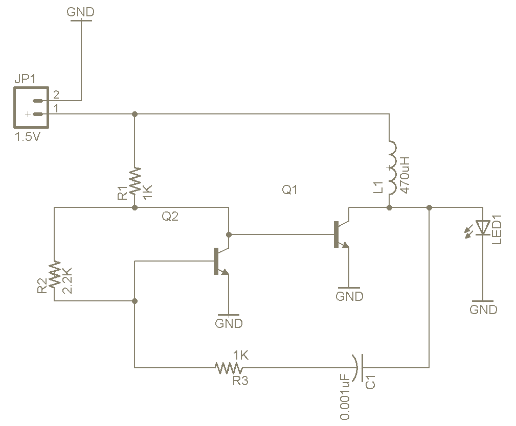
The Joule Thief is a straightforward and uncomplicated device, yet its functionality is remarkable. It can utilize a battery that is otherwise deemed unusable in any other electronic device, and it is very easy to construct on a breadboard...

Have you verified whether you can see the zero crossings on your input pin? It may be beneficial to write a sketch that toggles the LED on pin 13 every 50 or 60 zero crossings. This should result in...
The result displayed on the LCD is incorrect; the thermometer shows a reading of 414 degrees instead of the actual room temperature. Assistance is needed to determine whether the issue lies within the hex file or the sensor itself....

The circuit utilizes the extremely low input current (0.1 pA) of the CA3420 BiMOS operational amplifier. With only one 10 megohm resistor, it achieves a range from ±50 pA maximum to a full-scale sensitivity of ±1.5 pA. Additionally, by...

An NPN bipolar transistor is typically utilized for relay switching, particularly with 12V coil-rated relays, as it helps maintain circuit separation. A diode is also added to prevent issues. The necessity of driving the relay with a transistor depends...