
Lead-Acid-Battery Regulator For Solar Panel Systems

Solar panel systems integrated with lead-acid buffer batteries are designed to optimize energy storage and utilization, particularly in environments where sunlight may be intermittent. The configuration of these systems typically includes solar panels, a charge controller, a lead-acid battery, and an inverter.
Solar panels convert sunlight into electrical energy, which is then directed to the charge controller. The charge controller plays a critical role in regulating the voltage and current flowing from the solar panels to the battery, ensuring that the battery is charged efficiently while preventing overcharging that could damage the battery.
In scenarios of low sunlight, the system is designed to maintain the battery's charge through various strategies, such as utilizing energy stored during sunnier periods or implementing smart charging techniques that optimize the charging process even with minimal input. The lead-acid battery serves as a buffer, storing energy for use during cloudy days or at night, thus ensuring a consistent power supply.
In addition, the inverter converts the stored DC (direct current) power from the battery into AC (alternating current) power, which is suitable for most household appliances. This ensures that the energy harvested from the solar panels can be used effectively, regardless of the time of day or weather conditions.
Overall, the integration of a lead-acid buffer battery in solar panel systems enhances energy reliability and efficiency, making it a popular choice for off-grid applications and areas with variable sunlight availability.The design of solar panel systems with a (lead-acid) buffer battery is normally such that the battery is charged even when there is not much sunshine. Thi.. 🔗 External reference
Related Circuits
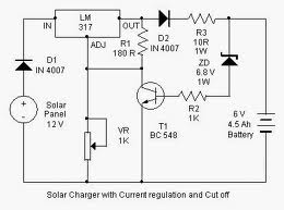
By adjusting the Adjust pin, the output voltage and current can be regulated. A variable resistor (VR) is connected between the Adjust pin and ground to achieve an output voltage of 9 volts to the battery. Resistor R3 limits...
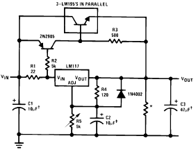
The following circuit diagram illustrates the application of the LM117 as a high current adjustable regulator. The LM117 is capable of supplying more than 1.5A. The LM117 is a popular adjustable voltage regulator that is designed to provide a stable...
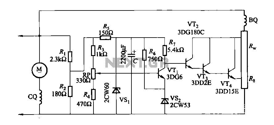
The DC generator automatic voltage regulator circuit is illustrated in Figure 7-53. This circuit is designed for a 40kW, 230V DC shunt complex machine, with a voltage change rate of up to 2.5 percent. In Figure 7-53, BQ represents...
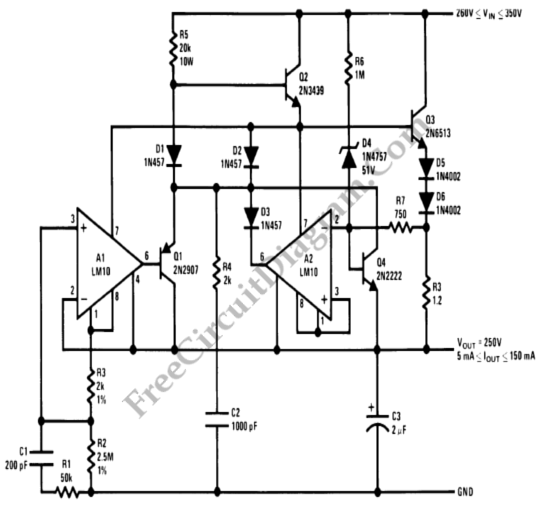
This circuit is a high voltage regulator that features foldback current limiter protection. It utilizes the LM10 comparator along with a voltage reference in its core design. The high voltage regulator circuit is designed to maintain a stable output voltage...
There is growing interest in utilizing PC and workstation platforms for reactive sound synthesis and processing applications. However, few operating systems are designed to provide real-time performance, and vendors typically do not guarantee or specify the expected performance levels...
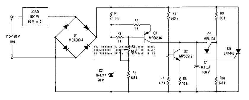
The circuit is an open-loop RMS voltage regulator designed to deliver 500 watts of power at 90 V RMS, maintaining good regulation within an input voltage range of 110-130 V RMS. When the input voltage is applied, capacitor C1...