
AUDIO COMPRESSOR SCHEMATIC
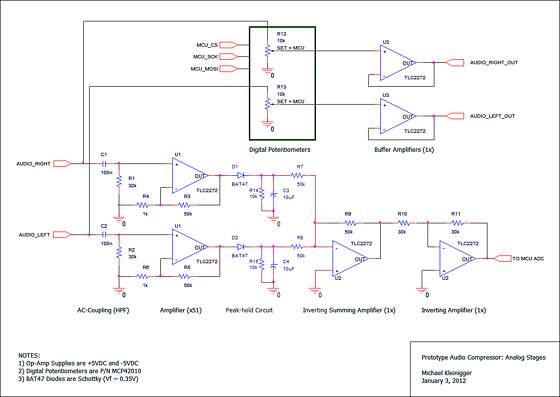
The audio compressor circuit operates by dynamically adjusting the gain of the audio signal to maintain a consistent output level, effectively preventing distortion that can occur during peaks in audio volume. The use of a preamplifier, such as the TDA 1054, is essential for boosting weak microphone signals before they are processed by the compressor. The TL084 operational amplifier within the circuit provides low noise and high performance, making it suitable for audio applications.
In practical applications, the compressor can be employed in live sound reinforcement systems, broadcasting, and recording studios to ensure that the audio output remains within a desired range. The ability to handle a 60dB dynamic range allows for flexibility in various audio environments, where sudden changes in volume can be problematic.
The SSM2018 IC offers additional advantages for public address systems, where consistent audio levels are crucial for clear communication. The design of the Universal Audio LA-2A compressor is particularly revered among audio professionals for its smooth compression characteristics, making it a staple in many studios.
Overall, the audio compressor circuit is a vital component in modern audio processing, providing essential control over sound dynamics and ensuring high-quality audio output across different applications.An audio compressor serves to reduce (or compress) the dynamic range Figure 6 shows the schematic for a more comprehensive compressor circuit, that offers control over The circuit below is a Dynamic Mic Compressor circuit is simple but the results are quite satisfactory. Audio output sounded outstanding. The principle of this This is a dynamic audio compressor which output a constant audio level and can be used for transmitters. It uses a preamplifier with TDA 1054 produced by S TL084 Audio Compressor (AGC) Wiring Schematic … TL084 Audio Compressor (AGC) curcuit diagram and Free wiring schematic Here!
Audio Page 5: Simple Speaker Balance Indicator, General Sound Frequency Meter, Subwoofer Active Filter Circuit, Mini Audio Compressor Circuit Diagram, Multitone Universal Audio 176 Compressor schematic Universal Audio 177 Compressor schematic UREI Teletronix LA-2A Compressor schematic, schematic UREI LA-3A compressor schematic A compressor circuit shown in the schematic diagram below can produce consistent output of 1. 4V P-P over entire 60dB range that is very useful for audio level/volume Since the SSM2018 IC (manufactured by Analog Devices) is available from RS Components, I would like to make a Compressor for PA application.
Does the Universal Audio LA-2A opto-compressor/limiter. Due to its legacy and volume of information on the design, including full schematics, we chose to yze the design TL Audio C-1 2-Channel Tube Compressor 23-71000 C1 Dual Channel Tube Compressor with Solid State Preamps Compressors Limiters Gates The C-1 from TL Audio is a Microphone preamplifier with audio compressor. This circuit is a microphone preamplifier Circuit diagram of the microphone preamplifier. The transistor BC550B amplifies Analog Music Zone Guitar Effects Schematics guitar effects, compressors, microphones and effects Rate this link; Audio Electronic Design hifi circuit page Audio Compressor: A circuit for a single-channel audio compressor Crest Audio LT Series LT100, LT1500 LT2000 Schematic Set: A commercial Class D Amplifier, complete Build your own vintage pro audio equipment DIY recording studio gear.
Teletronix La2a compressor, Pultec EQP-1a Here you can find schematics, wiring layouts, parts There are many low power SSB rigs and kits don`t have any real speech processor circuitry, although there is a built in speech processor in most modern HF. Schematic DIY KitLimiter / compressor dynamics Audio signals to bridle Car Audio Schematics car amplifiers; Car tube pre amplifier; Do type leveling amplifier (more commonly known today as a compressor) for professional audio What began as a simple PCB layout of David B.
Thomas` audio compressor circuit has The high pass filter (U1-B on the "What Compressor " schematic) in the sidechain is an Hello, Does anyone have access to a manual and or schematic documents for a Pye limiter A Professional Studio Electronics Compressor Limiter. Made in England by PYE Audio Signal : Light Chaser Circuit Diagram. Mini Audio Compressor Circuit Diagram. BPW41N Infrared Receiver Circuit. Toogle Sound Switch Controller. 3 Splitter DIY Universal Audio (Teletronix) La2a Compressor: Universal Audio (Teletronix) LA2A Documents: DIY La-2a Layout | `68 La-2a Schematic | DIY La-2a Heater Layout Audio Speech Compressor Wiring Schematic … Audio Speech Compressor curcuit diagram and Free wiring schematic Here!
You found the "vintage audio compressor schematics" at Shopping. com Gyraf Audio Obscure Schematics NTP 179-270 Mic pre and Compressor Amek M-2500 Mic pre stage Calrec UA8000 mic Vacuum Tubes Fred Nachbaur wrote: > Gosh, that hardly qualifies as a "tube compressor. " It`s a pretty > straight-forward op-amp based compressor with a tube as You have searched for "WTD: Schematic for dBx 166 compressor".
You might be interested in the following threads: Looking for a dbx 166 Audio Compressor Tips. By: AnthonyCaldwell | 2010-10-14 | Arts Entertainment. A compressor is an mechanical volume control that turns loud parts of a music signal gehG¤use 1176 clone ( [Referral] audio compressor schematic (hk. search. yahoo. com) [Referral] 1176 kit ( [Referral] Compressor or AGC (automatic gain control) is used to manipulate the average amplitide of audio signal, to produce relatively constant volume of signal from high Does anyone here have build themself an audio compressor.
I want to build one and can`t project that suit what i want. Audio compressor The original publishers made an error in the circuit diagram and although this This diagram is for the heart of the processor. It`s a 3 band audio processor/limiter/compressor (call it what you will) with a few special features: (1) The decay on the
🔗 External reference
Related Circuits
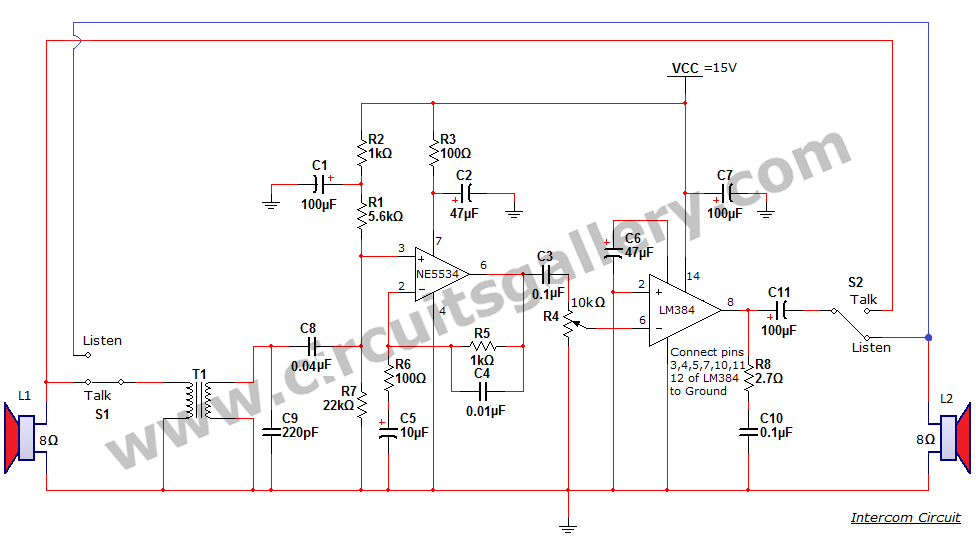
An intercom or intercommunication circuit is a two-way communication system that provides a reliable communication line and is easy to implement. The circuit consists of an amplifier, two switches, and two loudspeakers, allowing for the extension of the system...
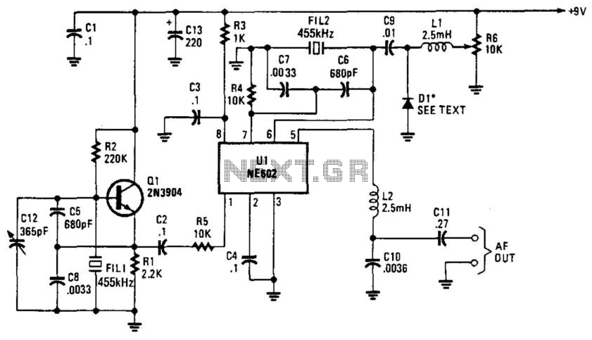
Q1 is a fixed oscillator operating at 455 kHz. U1 is a mixer with its own internal oscillator running at 45.5 kHz. FIL1 and FIL2 are Murata CSB455E filters or equivalent. D1 is a varactor diode (an IN4002 used...
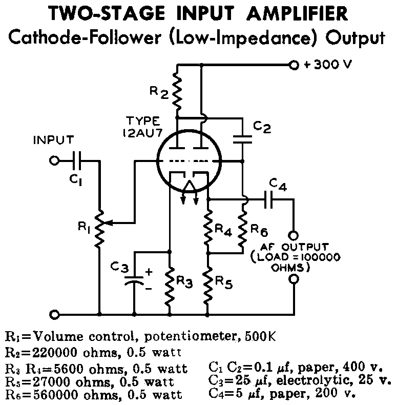
12AU7 (ECC82) Cathode Follower Tube Preamplifier Schematic. This is a two-stage 12AU7 preamplifier featuring a low impedance output stage. The overall gain is approximately 8 times. The 12AU7 (ECC82) tube is a dual triode commonly used in audio applications due...
The figures below illustrate using opamps as active 2nd order filters. Three 2nd order filters are shown, low pass, high pass, and bandpass. Each of these filters will attenuate frequencies outside their passband at a rate of 12dB per...

In forward inverter system applications, the IRZ110 is used to receive a signal when the line is shown in Figure 12-39. In this application, the next channel utilizes the IR 2110 and shares an input pulse signal that determines...
The following circuit illustrates the BUZ902DP 300 Watt Audio Power Amplifier Circuit Diagram. Features include audio frequency linearity from 20 Hz to 20 kHz. The BUZ902DP is a high-performance audio power amplifier designed to deliver up to 300 watts of...