
Low distortion audio gain limiter

The described audio limiter circuit employs an operational amplifier (op-amp) configured as a comparator to regulate audio signal levels. The LIMIT LEVEL selector knob allows for user-defined control over the threshold at which limiting occurs. When the input audio signal exceeds this threshold, the op-amp's output transitions, activating an LED indicator. This activation leads to a rapid decrease in the resistance of a photoresistor, which is part of a feedback loop that influences the gain of the op-amp.
As the signal level falls below the set threshold, the LED deactivates, causing the photoresistor's resistance to increase. This change in resistance allows the op-amp to restore its gain to the predetermined level set by resistors R1 and R2. The circuit's design ensures that audio signals are maintained within a specified dynamic range, preventing distortion or clipping that can occur with excessive signal levels.
For optimal performance, the op-amp requires a dual polarity power supply, typically ±12 volts. This voltage range is essential for the op-amp to operate effectively within its linear region, allowing for accurate signal processing. The choice of components, including the values of R1 and R2, should be made based on the desired limiting characteristics and the specific application requirements. Overall, this audio limiter circuit is a valuable tool for maintaining audio fidelity in various electronic applications.The level at which the limiter kicks in audio can be adjusted with the selector knob LIMIT LEVEL. When this level is exceeded, the output of the half-LIMITING detector of the op-amp (used as a comparator) turns the LED causes the resistance of the photoresistor to decline rapidly. It is in tum causes the gain of Ie half LIMITED op-amp to decrease. When the signal falls below the desired limit, the light goes out, the resistance of the photocell increases and the gain of the op-amp back to its normal level LIMITED one set by the combination of resistors RI and R2 . A dual polarity power supply (± 12 volts is desirable) is required for the op-amp.
Related Circuits
This project involved the design of an audio amplifier capable of delivering substantial output power with minimal component count while maintaining high quality. The power amplifier section utilizes three transistors along with a few resistors and capacitors in a...
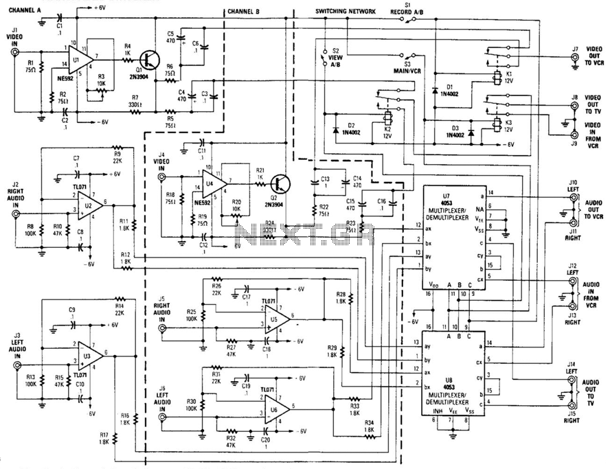
This circuit is a two-channel baseband video switcher. Buffer amplifiers U1/Q1, U4/Q4, and associated components produce a buffered 75-ohm video signal, which is routed to the switching network K1/K2/K3. Relay K1 selects either of the two video amplifiers and...
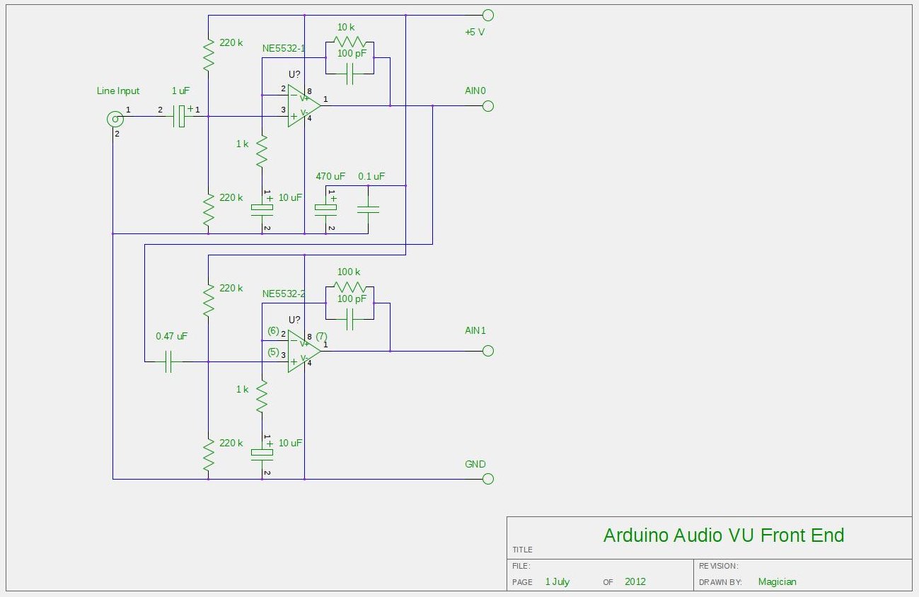
After experimenting with a stereo version of the VU meter described in a previous blog post, a studio-grade VU meter is now being presented. This meter features 24 steps, spaced equally every 3 dB, and covers a wide dynamic...
This audio mixer circuit does not utilize a low impedance input to mix non-ideal sources; instead, it employs multiple amplifiers to provide ideal sources prior to mixing through simple resistors. An ideal source is characterized by low impedances, which...
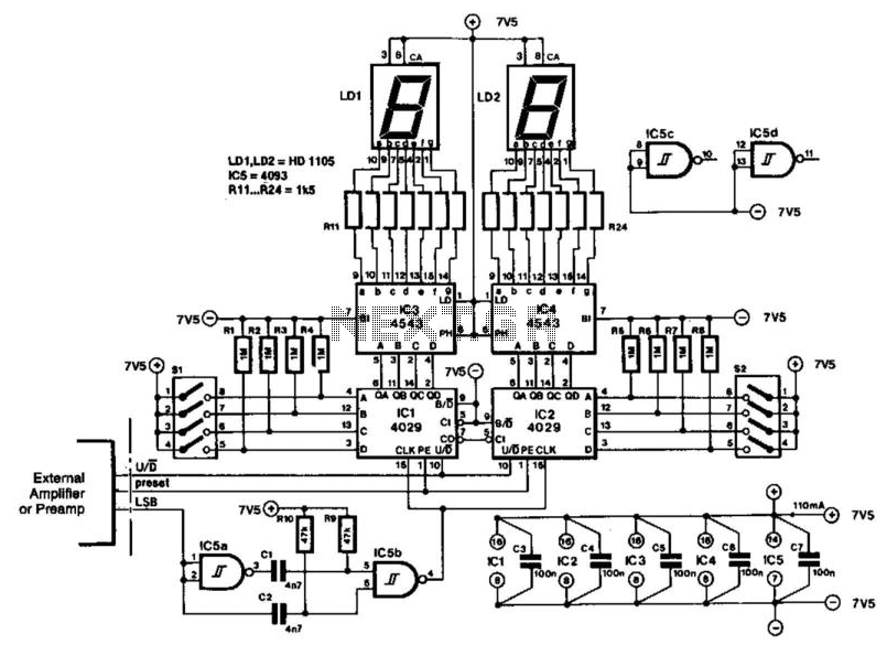
The indicator is designed for use with an audio amplifier or preamplifier, but it can also be utilized in other applications requiring rapid counting of steps or changes. To avoid interference with the audio signal, the circuit operates in...
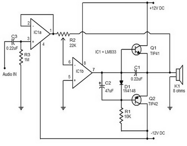
The 15W Class B audio amplifier circuit presented here is a straightforward Class B audio amplifier utilizing the TL082 operational amplifier, along with TIP41 and TIP42 transistors. The LM833 is a dual amplifier known for its high scanning speed...