
LM3900 Audio Mixer Schematic Diagram

The audio mixer circuit utilizes the LM3900 quad op-amp, which is a versatile component known for its low noise and high performance in audio applications. The circuit configuration allows for the integration of two line-level inputs and two microphone inputs, making it suitable for a variety of audio mixing scenarios. The operational amplifiers in the circuit serve to buffer the inputs, providing the necessary gain and ensuring that the signals are adequately processed before mixing.
The gain adjustment feature is critical for optimizing the output level according to the requirements of the connected equipment. By varying the values of resistors R7 through R10, the gain can be tailored to achieve the desired amplification, allowing for flexibility in handling different types of audio sources. This adjustment capability is essential in live sound applications or recording environments where different input levels may be encountered.
The high impedance output characteristic of this mixer circuit is advantageous, as it minimizes loading effects on the preceding stages in the audio chain. However, it is crucial to connect the output to processing equipment that can accommodate high impedance inputs to ensure optimal performance and signal integrity. This design consideration is vital for maintaining audio quality and preventing signal degradation.
In summary, this audio mixer circuit effectively combines multiple audio sources while providing the necessary gain and maintaining signal integrity through the use of the LM3900 quad op-amp. The ability to adjust gain and the high impedance output make it a valuable tool in audio mixing applications.This audio mixer circuit doesn`t use a low impedance input to mix no ideal sources, but use many amplifiers to provide ideal sources before mixed through simple resistors. Ideal source means a sources with low impedances, make the interaction between signals in the output doesn`t affect the input.
Please note that this mixer circuit has high impe dance output, so you`ll need an next processing equipment with appropriate input specs. This audio mixer circuit is designed around an LM3900 quad op amp and combines 2 line and 2 mike inputs and sums them at the output terminal. To vary the gain (around +23 dB), we can change the R7 through R10. You are reading the Circuits of LM3900 Audio Mixer And this circuit permalink url it is 🔗 External reference
Related Circuits
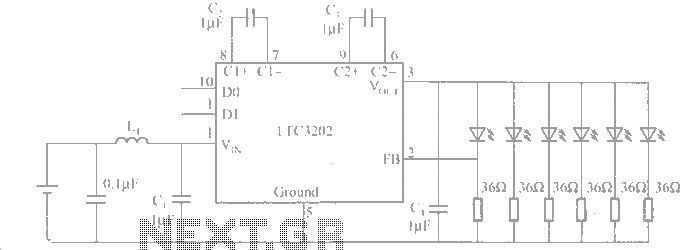
The LTC3202 is a device from Linear Technology that eliminates the need for a charge pump gated oscillator. It is designed as a charge pump for driving white LEDs powered by a lithium-ion battery. To address noise issues, the...
The simplest method of detecting metal is through a beat frequency oscillator. The circuit consists of two balanced oscillators: one serves as the detector element while the other provides a reference signal. The reference oscillator frequency is set to...
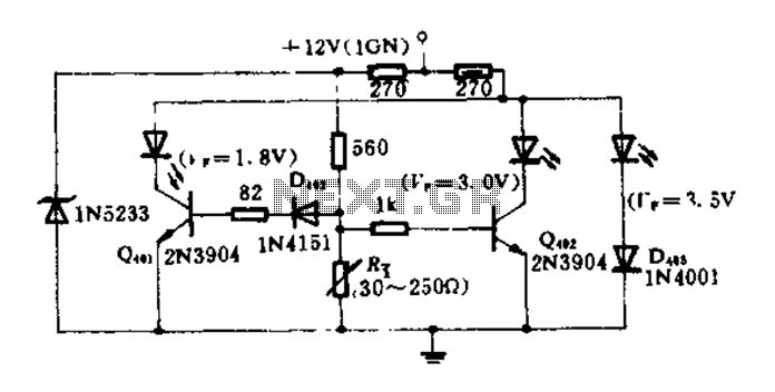
The circuit diagram illustrates how an oil pressure sensor is transformed into a variable resistor, denoted as Rt. Variations in Rt lead to changes in the biasing of each transistor, which in turn controls three LEDs (red, yellow, and...
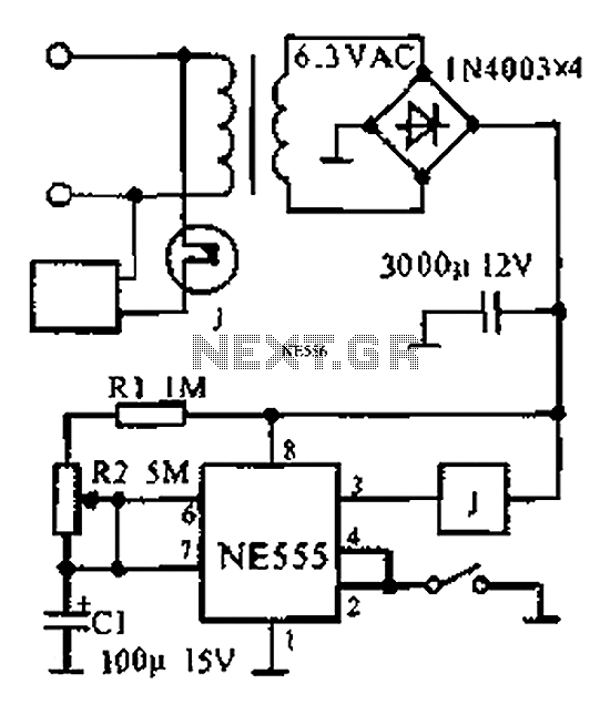
The provided information indicates that when the power supply operates between 0 to 1 hour, an AC circuit diagram is established using a 555 timer configured as a one-hour timer. The relay utilized is a J 212 IRC MR312C...
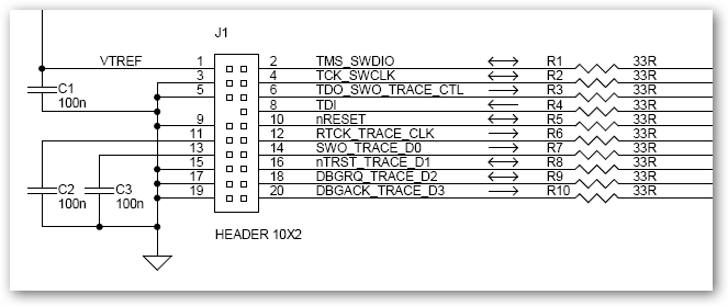
This interface schematic illustrates the JTAG, Serial Wire, and ETM interface circuits of ULINKpro. It can be utilized to analyze potential issues with the target hardware. The schematic represents the interconnections and functionalities of the JTAG (Joint Test Action...
The automatic sprinkler controller circuit consists of a +12 V power supply circuit, a light control circuit, and an irrigation control circuit, as illustrated in the accompanying figure. The +12 V power supply circuit includes a knife switch (Q),...