
30 Watt Audio Power Amplifier
The audio amplifier circuit is designed for simplicity and efficiency, utilizing a minimal number of components to achieve high performance. The core of the amplifier is the power amplifier section, which is based on a three-transistor configuration that allows for efficient amplification of audio signals. The shunt feedback configuration enhances linearity and reduces distortion, contributing to the overall sound quality.
The regulated power supply is critical for maintaining stable operation and minimizing noise. The LM317T adjustable regulator is a versatile component that, when augmented with a PNP transistor, can effectively handle the current demands of the amplifier. This configuration ensures that the amplifier can deliver consistent performance even under varying load conditions.
The preamp stage is designed with flexibility in mind, featuring a volume control at the input to maximize the input overload margin. The Baxandall-type tone control stage allows users to tailor the audio output to their preferences, enhancing the listening experience. The use of a bootstrapped circuit design in this stage ensures low noise and high fidelity, making it suitable for a wide range of audio sources.
Overall, this audio amplifier project exemplifies a balance between minimalism and performance, allowing for a high-quality audio experience with a straightforward design approach. The careful selection of components and configuration ensures that the amplifier can meet the demands of modern audio playback while remaining accessible to constructors with varying levels of expertise.This project was a sort of challenge: designing an audio amplifier capable of delivering a decent output power with a minimum parts count, without sacrificing quality. The Power Amplifier section employs only three transistors and a handful of resistors and capacitors in a shunt feedback configuration but can deliver more than 18W into 8 Ohm with
0. 08% THD @ 1KHz at the onset of clipping (0. 04% @ 1W - 1KHz and 0. 02% @ 1W - 10KHz) and up to 30W into a 4 Ohm load. To obtain such a performance and to ensure overall stability of this very simple circuitry, a suitable regulated dc power supply is mandatory. This is not a snag because it also helps in keeping noise and hum of the preamp to very low levels and guarantees a predictable output power into different load impedance.
Finally, as the amplifier requires only a single rail supply, a very good dc voltage regulator capable of supplying more than 2 Amps @ 40V can be implemented with a few parts also. Switch off the supply, disconnect the Multimeter and reconnect it, set to measure at least 1Amp fsd, in series to the positive supply (the possible use of a second Multimeter in this place will be very welcomed).
Those lucky enough to reach an oscilloscope and a 1KHz sine wave generator, can drive the amplifier to the maximum output power and adjust R3 in order to obtain a symmetrical clipping of the sine wave displayed. The Preamp sensitivity and overload margin were designed to cope with most modern music program sources like CD players, Tape recorders, iPods, Computer audio outputs, Tuners etc.
The source selecting switches and input connectors are not shown and their number and arrangement are left to the constructor`s choice. To obtain a very high input overload margin, the volume control was placed at the preamp input. After a unity gain, impedance converter stage (Q1) a negative-feedback Baxandall-type Bass and Treble tone control stage was added.
As this stage must provide some gain (about 5. 6 times) a very low noise, "bootstrapped" two-transistors circuitry with FET-input was implemented. This stage features also excellent THD figures up to 4V RMS output and a low output impedance, necessary to drive properly the Mini-MosFet Power Amplifier, but can also be used for other purposes. A very good and powerful Regulated Power Supply section was implemented by simply adding a PNP power transistor to the excellent LM317T adjustable regulator chip.
In this way this circuit was able to deliver much more than the power required to drive two Mini-MosFet amplifiers to full output (at least 2Amp @ 40V into 4 Ohm load) without any appreciable effort. A power Transformer having a secondary winding rated at 35 - 36V and 50VA (i. e. about 1. 4Amp) is required if you intend to use Loudspeaker cabinets of 8 Ohm nominal impedance. To drive 4 Ohm loads at high power levels, a 70 - 75VA Transformer (2Amp at least) will be a better choice.
These transformers are usually center tapped: the central lead will be obviously left open. For the stereo version of this project, R16 and C11 in the Preamp will be in common to both channels: therefore, only one item each is necessary. In this case, R16 must be a 1K5 1/2W resistor. The value of C11 will remain unchanged. 🔗 External reference
Related Circuits
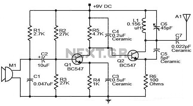
The moderate power FM transmitter circuit employs two transistors. The voice signals picked up by the microphone will be amplified by the transistor. The described FM transmitter circuit utilizes two transistors to facilitate the modulation and amplification of audio signals....

A photodiode can be utilized for high-speed digital transmission; however, it is necessary to provide a high-speed signal conditioner for this purpose. The amplifier circuit... A photodiode is a semiconductor device that converts light into electrical current. In high-speed digital...
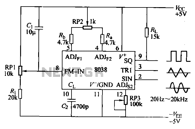
The ICL8038 function generator is an audio composition device that utilizes the ICL8038 integrated circuit. The resistance Ri potentiometer RP1 is used to determine the flow potential. Typically, the output is set to approximately 2Vcc / 3. Lowering the...

The amplifier utilizes a single MRF245 transistor and delivers 80 W of output power with a gain of 9.4 dB across the frequency range of 143 to 156 MHz. The circuit design for the amplifier featuring the MRF245 transistor is...
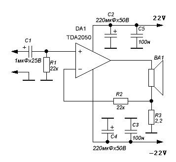
TDA2050 audio amplifier circuit diagram. The circuit incorporates environmental protection, where the output signal travels through connecting cables and the speaker’s network. In this case, the reactance of the circuit section connected to pin 4 of the chip is...
Here a simple design for an attractive tone. They operate on a passive principle, ie without amplification. The circuit only weakened and therefore require no power. As can be seen, the circuit is built with two T-filters in the...