
Low/Floating/High Detector
The dual low/floating/high logic state detector circuit is designed to provide clear visual feedback on the state of a digital signal pin, making it an invaluable tool for debugging and testing digital circuits. The use of two distinct LEDs allows for immediate identification of the signal state, facilitating quick troubleshooting.
The LMC6484 operational amplifier, chosen for its rail-to-rail output capability, ensures that the circuit can operate effectively across a range of input voltages, enhancing its versatility. The biasing arrangement using R6 and R7 is critical, as it establishes a reference point that allows for accurate detection of high and low states. The comparator configuration of the amplifiers enables precise threshold detection, ensuring that the circuit responds appropriately to varying signal levels.
The voltage divider formed by R11, R13, and R12 is essential for setting the detection thresholds. By adjusting R13, the designer can fine-tune the circuit's sensitivity, accommodating different logic levels or signal characteristics. This flexibility is particularly useful in environments where signal integrity may be compromised or where different logic families are in use.
The inclusion of R15 as an input protection resistor is a prudent design choice, safeguarding the operational amplifiers from potential damage during testing or debugging scenarios. This feature enhances the durability of the circuit, allowing it to withstand accidental misconfiguration without failure.
R14's role in limiting LED current is also significant. By calculating the appropriate resistance value based on the supply voltage and desired LED current, the designer can ensure optimal LED brightness while preventing excessive current that could lead to premature LED failure. This attention to detail in component selection and configuration contributes to the overall reliability and performance of the circuit.
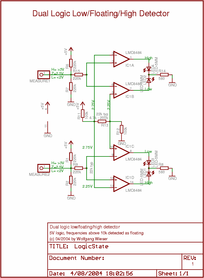
In summary, this dual low/floating/high logic state detector circuit is a well-thought-out design that balances functionality, reliability, and ease of use. Its clear visual indicators, robust protection features, and adjustable thresholds make it an essential component for anyone working with digital electronics.This circuit is a dual low/floating/high logic state detector which enables you to see the logic state of a digital signal pin. Each detector has two LEDs (typically a red and a green one) which indicate the state: red LED for high state, green LED for low and no LED for floating.
Frequencies up to 10kHz are properly handeled (low and high LED on) , higher frequencies (especially above 100kHz) are displayed like floating state (no LED running). The design is easily explained: National `s LMC6484 is a comparatively cheap rail-to-rail amplifier with guatanteed operation down to 3V. One DIL-14 package contains 4 amplifiers - just what is needed for two independent detectors. Using R6 and R7, the input is biased at 2. 5V (half supply voltage). In case the signal pin connected to the measure input is H/L, the voltage at the left side of R15 will rise/fall.
Using two amplifiers in comparator mode, this potential is compared to the threshold values available through the voltage divider R11, R13 and R12. R13 adjusts the potential difference between upper L limit and lower H limit. Voltages in between are considered heigher H nor L and hence floating. (R15 is used as input protection for the amplifier as suggested by the data sheed. Hence, it should not be harmful for the device to connect the measure pins when no power is applied. ) R14 is used to limit the current through the LEDs; for 5V and low current LEDs (2mA), I use 560Ohm resulting in about 4.
5mA LED current. Adjust that for 3. 3V operation and/or different LEDs. 🔗 External reference
Related Circuits
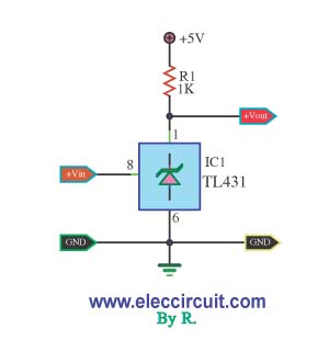
This is a simple pressure level check circuit, utilizing the integrated circuit TL431. It operates with a power supply of 5 volts for the digital circuit. The general feeding signal is... The circuit is designed to monitor pressure levels by...
This page features basic, visible light photo-detector circuits that can be used to detect trains. These methods would normally be used with the photo sensor mounted between the rails. The described photo-detector circuits are designed to detect the presence of...
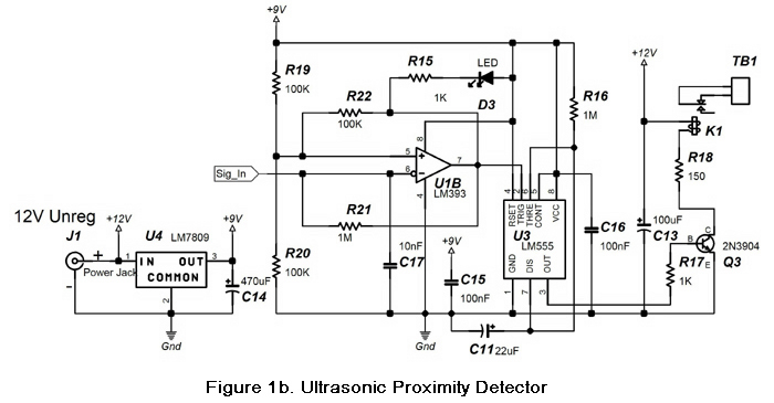
The circuit in Figures 1a and 1b illustrates the schematics of an ultrasonic proximity detector with a maximum detection range of approximately 6 feet. When an object passes in front of the ultrasonic transceiver board, the contacts of relay...
This circuit gives out an alarm when its sensor is wetted by water. A 555 astable multivibrator is used here which gives a tone of about 1kHz upon detecting water. The sensor when wetted by water completes the circuit...
This circuit is a Low-Light Level Drop Detector. It utilizes a self-biasing configuration to detect small changes in light levels. The Low-Light Level Drop Detector circuit is designed to sense minute variations in ambient light conditions, making it suitable for...
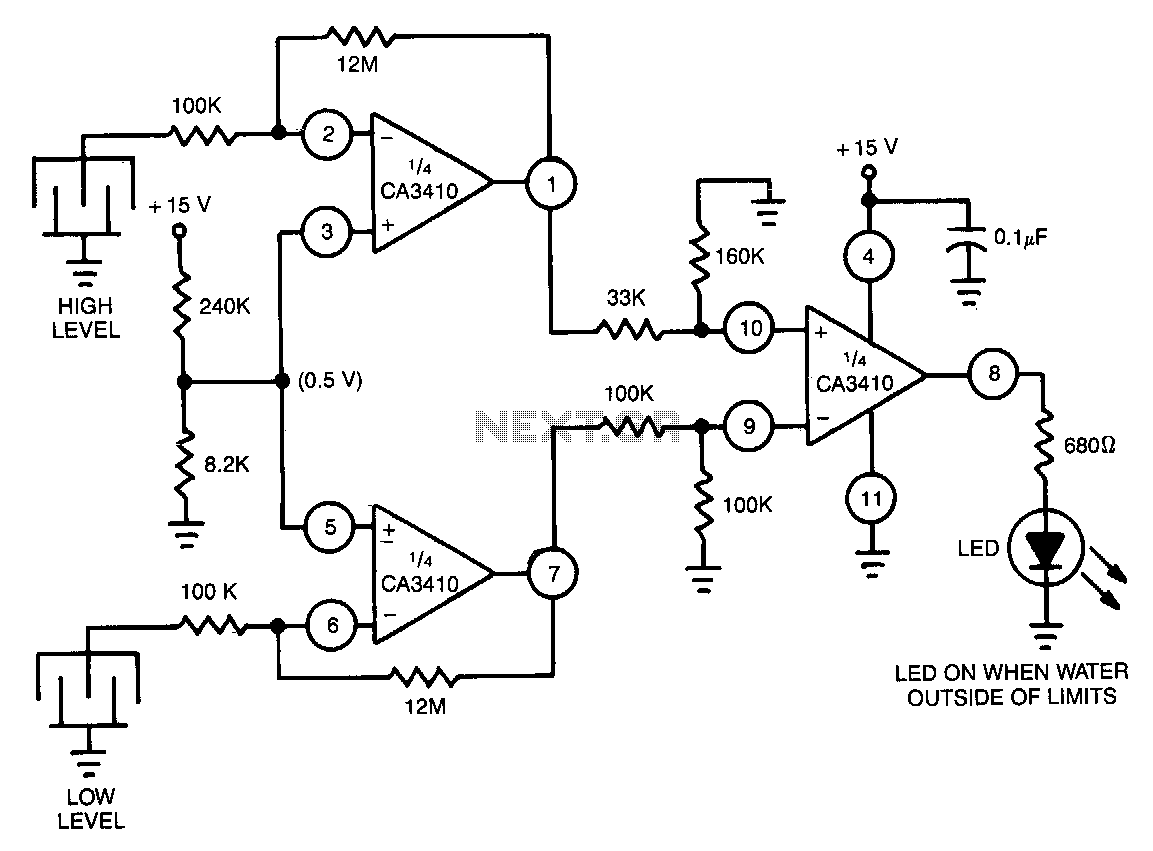
Utilizes the CA3410 quad BiMOS operational amplifier to detect small currents. Due to the low input current of the op-amp, a current as small as 1 pA flowing through the sensor will cause the converter's output to vary by...