
Ultrasonic Proximity Detector
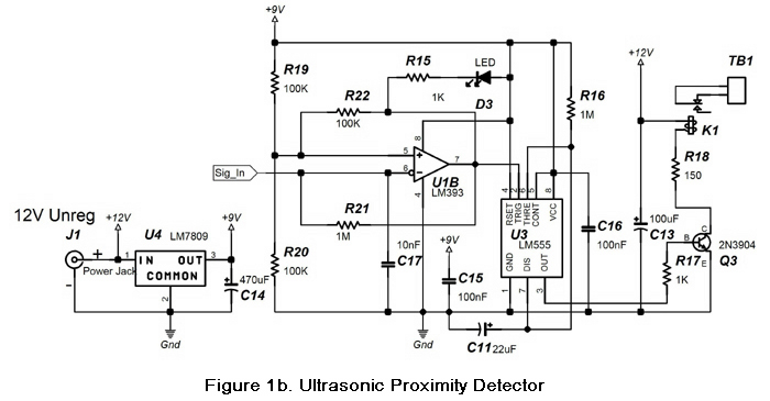
The ultrasonic proximity detector circuit operates primarily by transmitting ultrasonic waves at a frequency of 40 kHz using the transmitter. When these waves encounter an object, they reflect back to the receiver. The circuit is designed to continuously monitor for these reflections. The relay K1, which acts as a switch, is used to control an external device or indicator based on the detection status.
The oscillator circuit, composed of U2C, U2D, U2E, U2A, and U2F, generates the ultrasonic frequency and ensures that the transmitter emits a consistent signal. The use of multiple gates allows for the amplification of current, which is crucial for driving the ultrasonic transducer effectively. The stabilization period after power-up is a typical behavior of oscillators, where the frequency may take a moment to settle.
The signal processing section, including transistors Q1 and Q2, is essential for amplifying the weak reflected signals received. The voltage doubler circuit, consisting of D1 and D2, rectifies the amplified signal, allowing it to be used for further processing. The comparator U1A plays a critical role in detecting when the received signal exceeds a predefined threshold, which is adjustable via the sensitivity potentiometer R12.
Once the threshold is surpassed, the activation of U1B generates a 70 Hz oscillating signal, which is visually indicated by the LED. The one-shot circuit (U3) ensures that the relay remains engaged for a specific duration, as determined by the values of R16 and C11, thus providing a controlled response to the detection event.
The inclusion of capacitor C13 serves as a protective measure against inductive kickback from the relay coil, which can introduce noise into the circuit and lead to false triggering. The power supply arrangement, utilizing a 12 VDC transformer and a voltage regulator (U4), ensures stable operation of the circuit components. The physical layout, with the transmitter and receiver mounted on perfboard, is designed to optimize the detection range and performance of the ultrasonic proximity detector.The circuit in Figure 1a and Figure 1b are the schematics of an ultrasonic proximity detector. It has a maximum detection range of approximately 6 ft. When someone passes in front of the ultrasonic transceiver board, the contacts of relay K1 will close. The relay will remain energized while the device continues to detect a reflection. When there is no reflection, the relay contacts will open after 20 seconds. Photo 1 shows the assembled circuit on an experimenter`s breadboard. U2C forms a 40 KHz oscillator (figure 3 shows the 40 KHz crystal assembly). This oscillator is connected to U2D and U2E while the inverted oscillator signal (U2B) goes to U2A and U2F. These parallel gates provide more current and drive the ultrasonic transmitter. Note that it may take a couple of seconds after the power is applied for the oscillator to stabilize.
Q1 and Q2 amplify the reflected 40 KHz signal picked up by the ultrasonic receiver by 2500. Q2 is capacitively coupled to the voltage doubler formed by D1 and D2. The rectified signal is connected to the negative input of voltage comparator U1A. R12 (the Sensitivity potentiometer) sets the threshold voltage for U1A. When the threshold voltage is exceeded, the open collector output of U1A goes high-impedance. This enables the 70 Hz oscillator formed by U1B. When this oscillator is on, the LED glows and the one-shot formed by U3 is repeatedly triggered. The output duration of the one-shot is set by R16 and C11 and is equal to 1. 1*R16*C11 seconds. U3`s output turns on Q3. As a result, K1 closes its normally open contacts. C13 dampens the inductive kickback when K1 is turned off, preventing the circuit from triggering due to this noise source. The unit is powered by a 12 VDC 200mA unregulated wall transformer. U4 provides a regulated 9VDC to power the circuit. Device pinouts are shown in Figure 2. The 40 KHz transmitter and receiver are mounted 4 inches apart on a piece of perfboard (see Photo 2 below).
🔗 External reference
Related Circuits
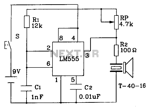
The circuit operates at a distance of 3 feet from the oscillating pulse output of a 555 timer generating a 40kHz signal, driving a T-40-16 transducer to emit ultrasonic signals at the same frequency. The circuit is powered by...
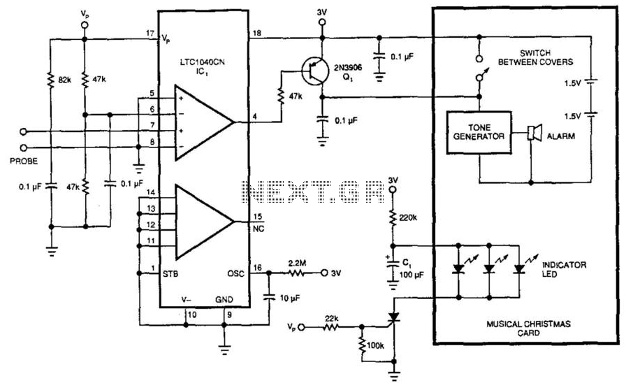
This circuit was originally designed to detect low water levels in a Christmas tree stand, but it can also be utilized as a water-level detector for pump controls and water sensors in garden and lawn applications. It employs a...
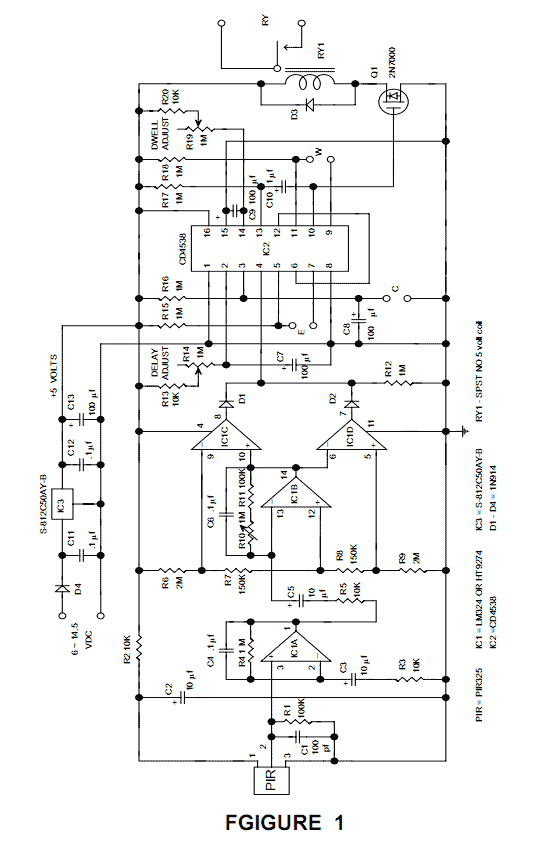
The GLMDA is designed to detect the motion of a human or animal both in daylight and at night and to provide a normally open relay output that can be used to activate many types of loads. The GLMDA...
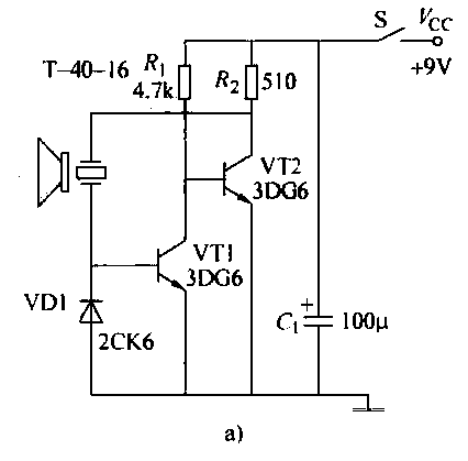
The ultrasonic transmitter circuit T-40-16, along with various discrete components, functions as a feedback sensor. The transistors VT1 and VT2 create a robust positive feedback oscillator that converts an electric signal into an ultrasonic oscillation signal, with the oscillation...
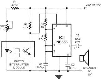
This smoke detector utilizes a 555 timer circuit along with common electronic components. The photo interrupter module serves as the smoke detection element, while the 555 timer is configured in astable mode to function as an audio frequency oscillator,...
The human approach detector circuit consists of an integrated operational amplifier, a gate circuit, and a resistor-capacitor unit as illustrated in the diagram. The 1 MHz oscillator is composed of a reverser T1, a 1 MHz crystal oscillator, and...