
low frequency oscillator

The RC phase shift oscillator is a fundamental circuit widely used in various applications such as signal generation, audio frequency generation, and waveform synthesis. The configuration consists of a single bipolar junction transistor (BJT) that serves as the active amplification element, while the passive components (resistors and capacitors) form the phase shift network necessary for oscillation.
In this oscillator, the phase shift is achieved through a combination of resistors (R1 and R2) and capacitors (C1 and C3), which are arranged to provide a total phase shift of 180 degrees at the desired frequency. The feedback capacitor C2, connected from the collector to the base, reinforces the oscillation by providing the necessary positive feedback.
The oscillation frequency is primarily determined by the values of the resistors and capacitors in the timing network. The relationship between these components can be derived from the standard formula for the frequency of an RC phase shift oscillator, which typically involves the time constant of the RC network.
In practical applications, adjustments to the preset resistor RV1 allow for fine-tuning of the oscillation start point, ensuring that the circuit can reliably commence oscillation under varying conditions. The simulation results obtained from LTSpice IV provide a visual representation of the output waveform, which can be analyzed for characteristics such as amplitude stability and frequency accuracy.
The ability to measure the oscillation frequency accurately is crucial for applications requiring precise timing and frequency control. The method of using cursors in the simulation software to measure the time period of the waveform is a standard practice that enhances the understanding of the oscillator's performance. The resultant frequency of just under 8 Hz indicates that this circuit is suitable for low-frequency applications, where stability and reliability are paramount.
Overall, the design and simulation of the RC phase shift oscillator exemplify essential principles in electronic circuit design, showcasing the interplay between active and passive components in generating oscillatory signals.The circuit is a standard RC phase shift oscillator using a single bipolar transistor as the active element. When power is applied regenerative feedback is applied via C2 from collector to base of the transistor.
The timing components, R1, R2, C1 and C3 dictate the oscillation frequency. In use preset RV1 is adjusted so that oscillation just begins . With values shown full amplitude oscillation takes about 4. 8 seconds (see diagram below). This oscillator is designed and simulated on LTSpice IV. Once simulated click the "probe" cursor on the output wire "Vo", the above waveform is produced. To calculate the frequency, place your mouse on the graph where oscillations have reached full amplitude and draw a rectangle, ensuring maximum and minimum amplitude is enclosed within the rectangle. The diagram below shows such a zoomed portion of the output waveform, starting around 5. 6 seconds into the simulation. To add cursors left click on the name of the output waveform, this is called "V(vo)". A single cursor is added to the graph which can be moved with the mouse or keyboard arrows. Now right click the mouse on the Vvo waveform. In the window that appears click on the attached cursor menu and change to "1st & 2nd". Now two cursors will be visible and controllable. Make sure both cursors pass through the zero volt horizontal meridian and measure one output cycle. A sub window allows you to read the value as shown above, for this oscillator the time for one cycle is 127.
2ms and frequency a little under 8Hz. 🔗 External reference
Related Circuits
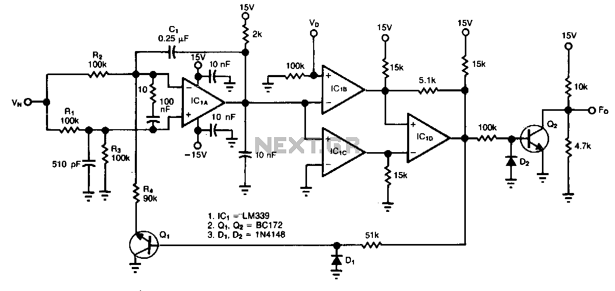
The circuit accepts two positive voltage inputs, VN and Vv, and provides a TTL-compatible output pulse train whose repetition rate is proportional to the ratio VN/V0. The full-scale output frequency is approximately 100 Hz, and the linearity error is...
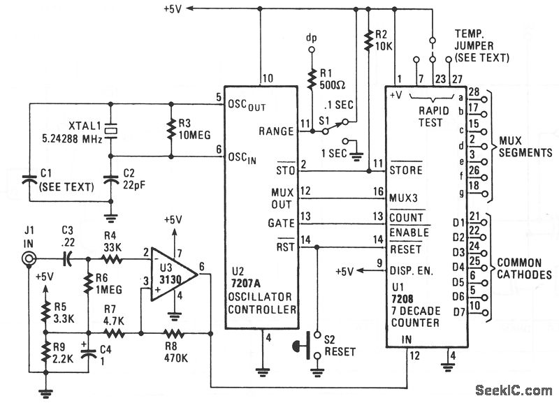
The circuit comprises an ICM7208 seven-decade counter (U1), an ICM7207A oscillator controller (U2), and a CA3130 biFET operational amplifier (U3). IC U1 counts input signals, decodes them into a 7-segment format, and outputs signals that drive a 7-digit display....
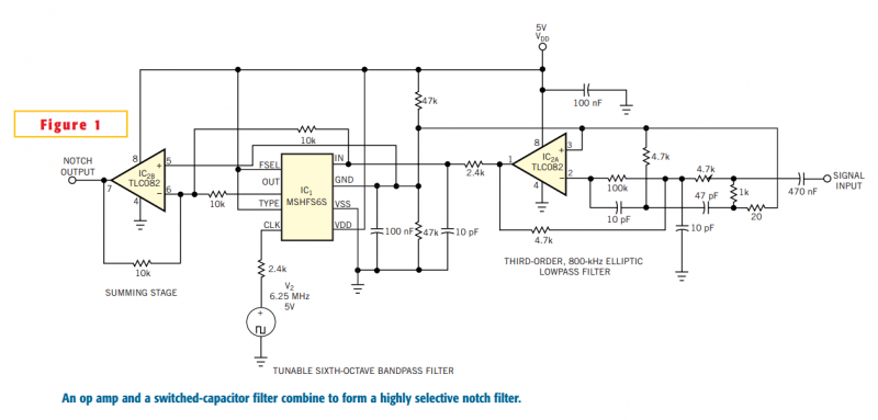
Although you can obtain universal, resistor-programmable switched-capacitor filters that are configurable as notch filters, most cannot operate at bandwidths higher than 100 kHz. Further, the typically 16- to 20-pin packages do not include a continuous-time, antialiasing filter to prevent...
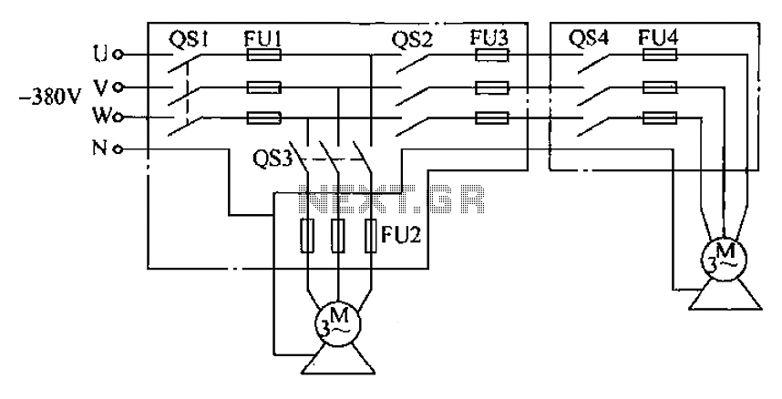
The agriculture and electrical power harrow plow power cord must consist of four rubber cables, with one core wire designated as the ground wire. The traction machine housing must be properly grounded. The two traction power machines are connected...
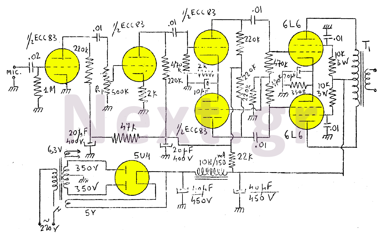
The amplifier in this design is rated at 30 Watts and is intended for use with a microphone. It is compatible with a crystal microphone and can be utilized for speeches, lectures, as a transmitter modulator, and in applications...
One example of the phase shift oscillator is the Bubba oscillator. This oscillator achieves a 45-degree phase shift for each section from a quad op-amp package. The Bubba oscillator is a type of phase shift oscillator that utilizes a...