
Low line loading ring detector
The H11BX522 is a photodarlington optocoupler that is designed to provide electrical isolation between its input and output while allowing for signal transmission. It consists of a light-emitting diode (LED) and a photodarlington transistor housed within a single package. The device is particularly suited for applications requiring low line current loading, making it ideal for interfacing low-power control circuits with higher voltage systems.
The input side of the H11BX522 features an LED that emits infrared light when a forward current is applied. This LED is typically driven by a control signal, which in this case, requires a minimum input current of 0.5 mA to operate effectively. When the LED is energized, it emits light that activates the photodarlington on the output side.
The photodarlington configuration is characterized by its high current gain, allowing it to provide an output current of 1 mA with a relatively low input current. This high gain is beneficial in applications where the control signal is weak or where minimal power consumption is desired. The output transistor can switch larger currents and voltages, making it suitable for driving loads such as relays or other electronic devices.
The H11BX522 is designed to operate over a wide temperature range and has a high isolation voltage, ensuring safe operation in various environments. Its compact package makes it easy to integrate into a variety of circuit designs, contributing to its versatility in applications such as signal isolation, data communication, and control systems.
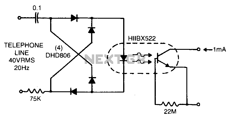
In summary, the H11BX522 photodarlington optocoupler is an efficient solution for low line current loading applications, providing reliable performance with minimal input requirements while maintaining electrical isolation between circuits.Low line current loading is provided by the H11BX522 photodarlington op-tocoupler which provides a 1 mA output from a 0.5 mA input. 🔗 External reference
Related Circuits
This circuit is an oscillator with LI being a 4-inch diameter coil consisting of 35 turns of #26 magnet wire. Metal in proximity to LI will cause the oscillator to shift frequency. An AM transistor radio is used to...
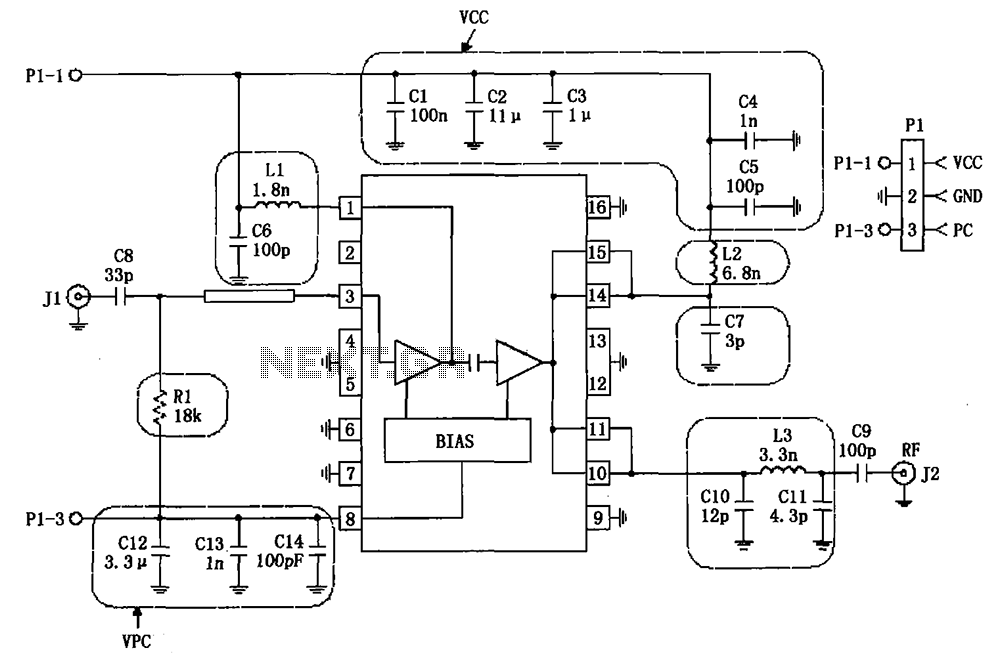
The RF2132 linear power amplifier circuit is depicted in the provided figure. A radio frequency (RF) signal enters through input pin 3 and is processed via a preamplifier. The final stage of the amplifier outputs a gain of 10....
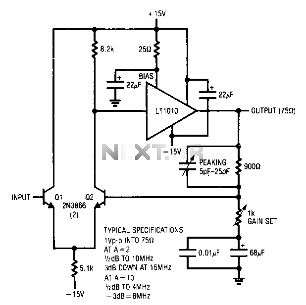
Q1 and Q2 create a differential stage that transitions into the LT1010. The capacitively terminated feedback divider provides a gain of 1, while permitting AC gains of up to 10. With a 20-ohm bias resistor, the circuit outputs 1...
This document explains how to connect lights so that they flash when the phone rings. This setup is particularly beneficial in noisy environments, such as workshops, where it is challenging to hear the phone ringing. The ring detection component...
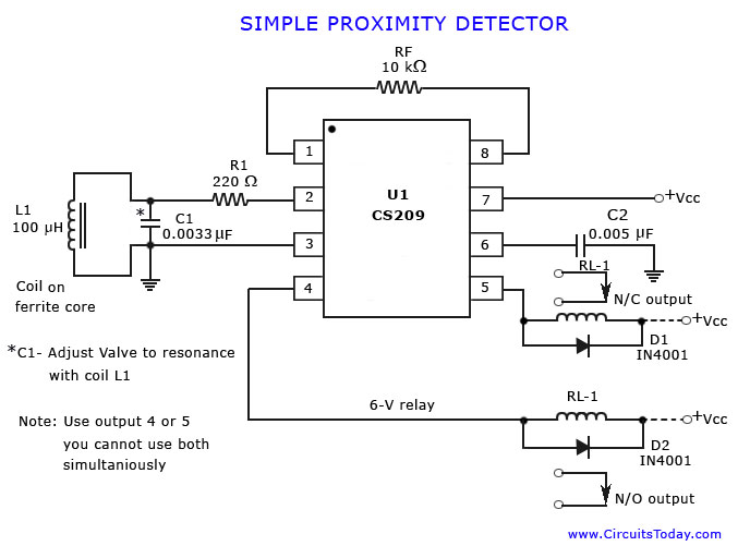
A simple proximity detector circuit diagram and schematic is presented, illustrating how to construct it using the proximity detector IC CS2009A, which is utilized for metal detector applications. The CS2009A is a versatile proximity sensor integrated circuit designed to detect the...
It is a relatively simple circuit, with which we can have optical and sound clue, when we have telephone ring in the line of telephone. The calls in the line, are changed in pulses of frequency 400 HZ from...