
Minimal metal detector
The oscillator circuit described utilizes an inductor (LI) formed by a 4-inch diameter coil with 35 turns of #26 magnet wire. The inductance of this coil, combined with its resistance and the circuit's capacitive elements, establishes a resonant frequency that can be influenced by nearby metallic objects. When metal is brought close to the coil, it alters the inductance, thereby causing a shift in the oscillation frequency. This frequency modulation can be detected using an AM transistor radio, which receives the oscillating signal and converts it into audible sound, allowing for the observation of frequency changes.
The choice of the MPS5172 transistor is critical as it serves as the active component in the oscillator circuit. This NPN transistor operates efficiently at low frequencies and can handle moderate power levels, making it suitable for this application. The circuit design may include additional passive components such as resistors and capacitors to stabilize the oscillation and improve the overall performance of the oscillator.
To construct the oscillator, the coil (LI) is connected to the transistor's collector, while the base is driven by a feedback network that may include a capacitor to ensure that the circuit oscillates. The emitter is typically connected to ground. The oscillation frequency can be fine-tuned by adjusting the values of the capacitors in the feedback loop or by changing the number of turns in the coil.
In summary, this oscillator circuit effectively demonstrates the principles of inductance and frequency modulation, with practical applications in proximity sensing and detection using standard AM radio receivers. Proper design and component selection are essential for achieving reliable performance in detecting frequency shifts caused by nearby metallic objects.This circuit is on oscillator with LI being a 4" diameter coil of 35 turns of #26 magnet wire. Metal in proximity to LI will cause the oscillator to shift frequency. An AM transistor radio is used to detect the frequency shift. The transistor is the MPS5172 or use a similar. 🔗 External reference
Related Circuits
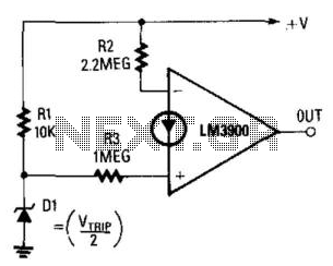
The output becomes high when the supply voltage drops below a threshold set by the zener diode D1. If D1 is a 5.6-V zener diode, the operational amplifier will activate when the supply voltage decreases to around 11 V....

The circuit utilizes a dual operational amplifier integrated circuit (IC), specifically the 1458, which contains two separate op-amps within a single package. In this configuration, the first op-amp functions as a voltage follower, directing its output to charge capacitor...
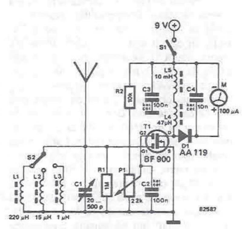
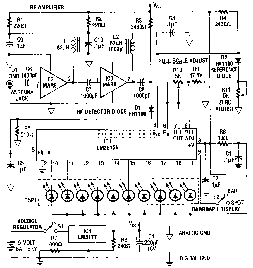
An RF field detector circuit suitable for measuring and verifying the power of antennas and transmitters can be constructed using transistors and common electronic components. This circuit employs a radio frequency transistor, specifically a MOS-FET with two gates. The...
This circuit is a simple IR detector for testing IR remote controllers. The circuit is based on one phototransistor which receives the IR beam. The NPN transistor works as an amplifier which feeds current to the LED. When this...
A circuit designed to extract and measure the modulated carrier of an infrared remote control. This circuit amplifies the entire received signal, allowing the waveform to be displayed on an oscilloscope or a frequency counter. It can measure modulation...
This RF detector is capable of locating low-power transmitters (such as bugs) that are not visible. It can detect the presence of a 1-mW transmitter from a distance of 20 feet, making it sensitive enough to identify even the...