
Low-noise broadband amplifier
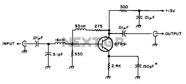
The amplifier circuit is designed to provide an effective gain of 10 dB, making it suitable for applications requiring signal amplification within the specified frequency range of 10 to 600 MHz. The 50-ohm matching ensures optimal power transfer and minimizes signal reflections, which is critical in RF applications. The choice of the BFR91 transistor is significant due to its low noise figure of 1 dB at 500 MHz, which enhances the overall performance of the amplifier by reducing the noise contribution to the amplified signal.
Power supply requirements are specified at 13 Vdc with a current draw of approximately 13 mA, which indicates a low power consumption typical for RF amplifiers. The design emphasizes the importance of minimizing lead lengths on the 150 pF emitter bypass capacitor, as longer leads can introduce unwanted inductance and affect the circuit's performance, particularly at high frequencies.
The use of a 16 nH coil, constructed from 2 turns of #26 enamel wire, is tailored for the specific inductance value required in the circuit. This coil is wound around a #40 drill bit, which serves as a form for maintaining consistent dimensions during construction. Additionally, the 93 nH inductor, made with 10 turns of the same wire, provides further inductive reactance necessary for tuning or filtering within the circuit. Both inductors are crucial for the stability and frequency response of the amplifier, ensuring that the desired operational characteristics are achieved. Proper construction techniques and component selection are essential for achieving optimal performance in high-frequency applications.The amplifier provides 10 dB of gain from 10-600 MHz and has a 1-to-l match at 50 ohms. The BFR91 has a 1 dB noise figures at 500 MHz, The circuit requires 13 Vdc at about 13 mA. Keep the leads on the 150 pF emitter bypass capacitor as short as possible. The 16 nH coil is 2 turns of #26 enamel wire on the shank of a #40 drill The 93 nH inductor is 10 turns of the same material. 🔗 External reference
Related Circuits
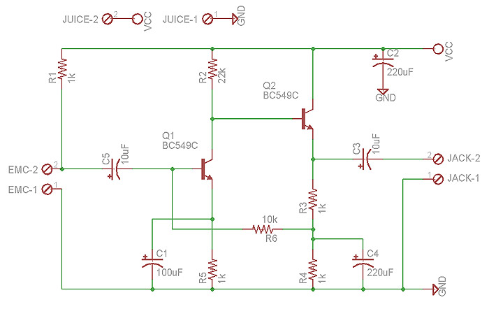
This preamplifier is designed for low-resistance sources such as moving coil heads (MC). The circuit employs three parallel double transistors, SSM2220 or MAT03, which form a differential amplifier that minimizes noise. When connected to an OP27 amplifier, it further...
What value of potentiometer should be used for the volume control of this audio amplifier circuit, and where should it be connected? Thank you. In audio amplifier circuits, the choice of potentiometer value for volume control is crucial for achieving...
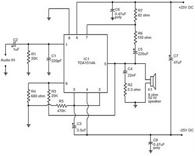
This is a mini-sized power amplifier rated at 2 watts OTL that utilizes the LM380 integrated circuit. It serves as a ready-made circuit for audio applications and communication, requiring minimal external equipment. The capacitor C6 can be selected from...
Level refers to the relative strength of the signal and is measured in decibels. LINE level sources are much-amplified signals compared to MIC (microphone) level signals. Line level typically ranges from -10 to +4 dBm in strength, while MIC...
This document provides a circuit diagram of a car stereo. It includes a circuit diagram of a Class B 15 Watts audio amplifier designed using a dual op-amp and a transistor. The 15 W Class B audio amplifier circuit...
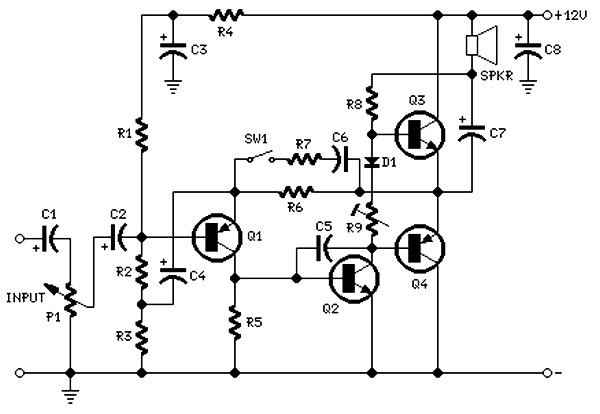
The circuit is intentionally designed using older type transistors to achieve harmonic distortion and to mitigate the challenges of sourcing high-quality components. The amplifiers can be easily powered by a plug-in wall transformer rated at 12V. When SW1 is...