
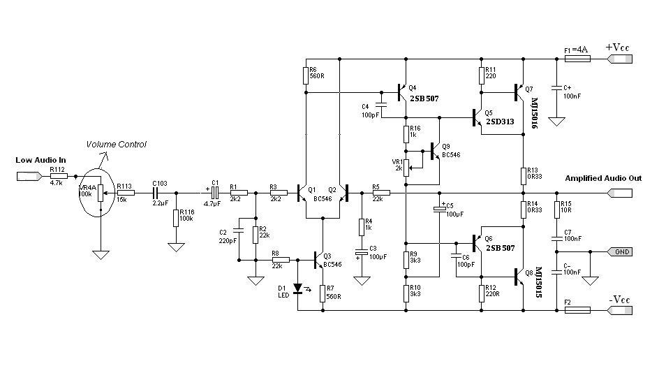
2 watt amplifier schematic diagram
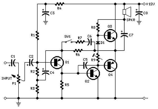
The circuit employs vintage transistors, which are known for their unique characteristics that can introduce desirable harmonic distortion, often sought after in audio applications for a warmer sound. The use of older components also simplifies the design and assembly process, as these parts are typically more readily available and cost-effective.
The power supply is a standard 12V wall transformer, which provides a convenient and reliable source of energy for the circuit. This voltage level is suitable for most audio amplifier configurations, ensuring that the transistors operate within their optimal range.
The inclusion of a bass boost feature, activated by the closure of switch SW1, enhances low-frequency response. This feature is particularly useful in audio applications where bass frequencies are crucial for overall sound quality. However, activating this feature can lead to a reduction in power at higher frequencies, necessitating an increase in the volume control to maintain a balanced audio output. This adjustment is critical to ensure that the overall sound remains clear and undistorted across the frequency spectrum.
Overall, the circuit design emphasizes simplicity and functionality, making it an effective solution for audio amplification while accommodating the nuances of sound quality through the use of harmonic distortion and bass enhancement techniques.The circuit is intentionally designed using old type transistor, it is to get the harmonic distortion and to avoid the difficulty of finding good components. Amplifier (s) can be easily supplied by plug-in wall transformer 12V. Closing SW1 bass boost is provided but, at the same time, volume control must be increased to compensate for the loss of
power at higher frequencies. 🔗 External reference
Related Circuits
The circuit diagram of a TV antenna is sourced from the technical information provided by Chinaicmart. For more detailed information or additional circuit designs, further inquiry may be necessary. The circuit diagram for a TV antenna typically consists of several...
A 12V to 20000V inverter circuit diagram (stun gun) is presented. This circuit generates a very high voltage and must be used with caution to prevent electric shock. The transformer can produce over 1000V and amplify the voltage by...
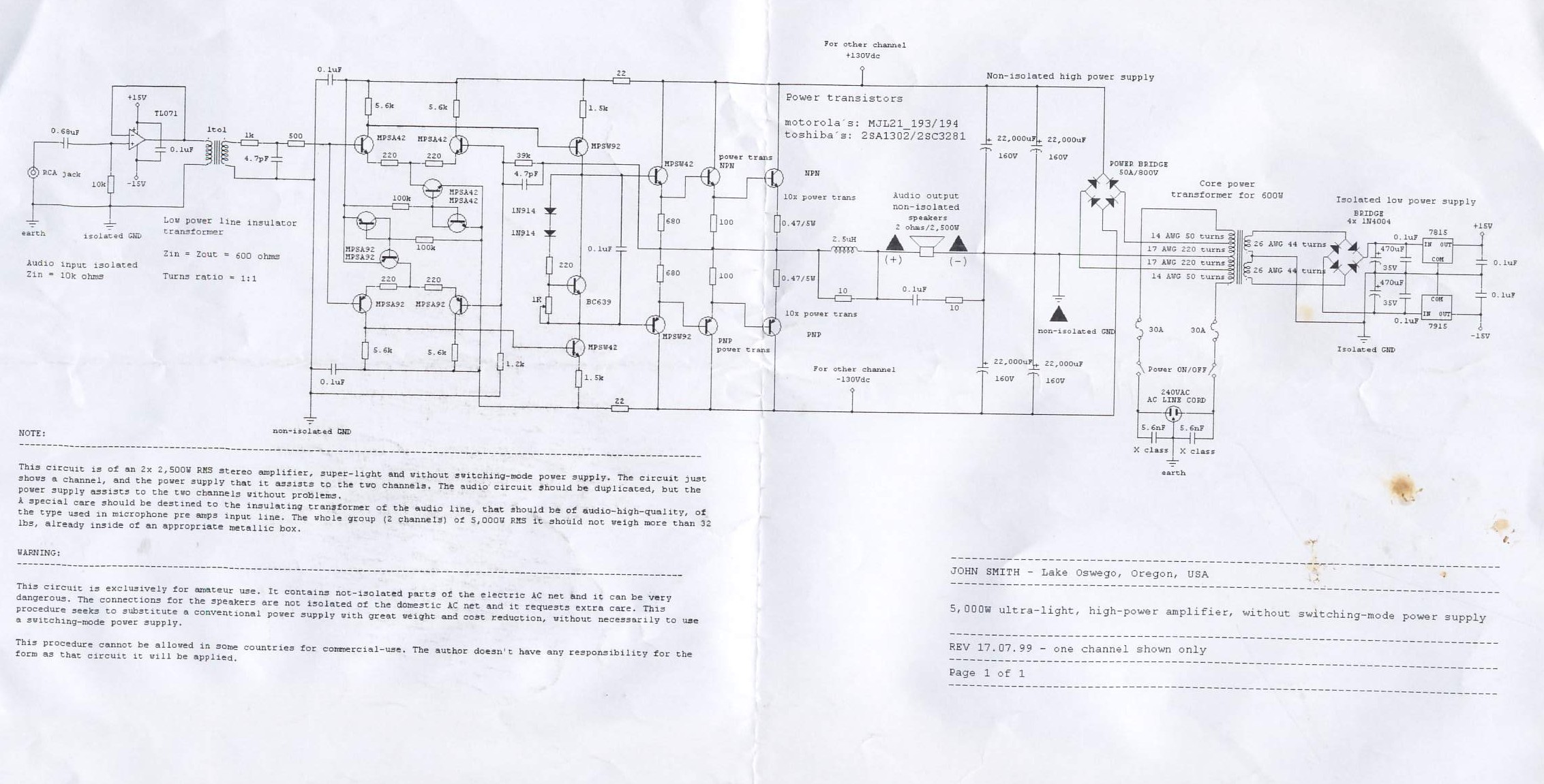
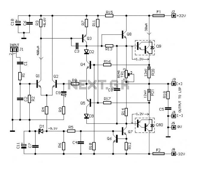
This circuit is for a 2x2, 500W RMS stereo amplifier that is super-light and does not utilize a switching-mode power supply. The circuit diagram displays only one channel, while the power supply is designed to support both channels. The...
Designing an audio amplifier from scratch using discrete components is an engaging task, as it enables users to create amplifiers that meet diverse requirements. Audio amplifiers can enhance low-level sounds from mobile devices, making them louder and more vibrant....
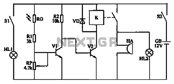
The circuit functions as a reminder system utilizing a photodetector amplifier circuit along with a sound and light alarm circuit, as illustrated in Figure 1. The photodetector amplifier circuit consists of a pilot light (HL1), a light switch (S1),...
The circuit of this 30W audio amplifier produces clear audio output quality. The circuit module does not have any improvements. It utilizes a Darlington pair in the transistor configuration. The 30W audio amplifier circuit is designed to deliver high-fidelity sound...
Warning: include(partials/cookie-banner.php): Failed to open stream: Permission denied in /var/www/html/nextgr/view-circuit.php on line 713
Warning: include(): Failed opening 'partials/cookie-banner.php' for inclusion (include_path='.:/usr/share/php') in /var/www/html/nextgr/view-circuit.php on line 713