
Low Power Amplifier LM386
The described power amplifier is intended for low-voltage applications, making it suitable for battery-operated devices where efficiency and minimal component count are critical. The design allows for the omission of capacitors C1 and C2, which simplifies the circuit without significantly affecting performance. This feature is particularly advantageous in portable applications where space and weight savings are essential.
The amplifier's gain is internally set to 20 dB when pins 1 and 8 are left open-circuit. This pre-set gain level ensures that the amplifier can provide a consistent output suitable for various input signals without requiring external adjustments. The configuration of the amplifier likely includes a feedback network that stabilizes the gain and enhances linearity, contributing to improved audio quality in applications such as portable speakers or low-power audio devices.
The circuit may incorporate additional components such as resistors for biasing and stability, as well as protection diodes to safeguard against voltage spikes, ensuring reliable operation in varying conditions. Given its design for low-voltage operation, the amplifier is likely optimized for low quiescent current consumption, thus prolonging battery life in portable applications.
Overall, this power amplifier is a versatile solution for applications requiring efficient amplification in compact, battery-powered devices.A power amp designed for use in low voltage, especially battery-operated, applications. For minimum parts count, C1 and C2 can be omitted. With pins 1 and 8 open circuit the gain in internally set to 20 dB. 🔗 External reference
Related Circuits
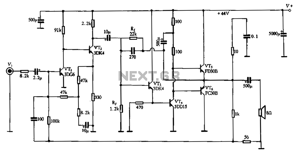
The circuit schematic depicted in Figure 2-3 illustrates a twin direct-coupled input amplifier stage composed of components OV, RLR, and VT2. The emitter of VT2 is connected to the base of VT3, utilizing local feedback to stabilize its DC...
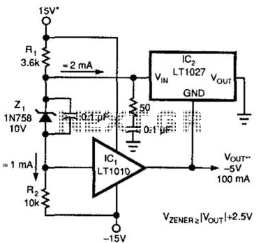
A method for enhancing the output current of a reference while also providing overload protection is illustrated. In this configuration, IC1 functions as a power buffer. The LT1027 regulates the output voltage (Vout) and ground to maintain a stable...
Photovoltaic (PV) technology involves the application of solar cells to convert sunlight directly into electricity. The provided manual on Photovoltaic Power Systems outlines practices in accordance with the 2005 National Electrical Code (NEC) relevant to PV power systems. This...
The amplifier operates primarily in the current domain. The first stage is a voltage controlled current sink. The second stage is a current-controlled voltage source. The fourth stage is a constant current sink. The main advantage of current domain...
An RF power amplifier is a type of electronic amplifier used to convert a low-power radio-frequency signal into a larger signal of significant power, typically for driving the antenna of a transmitter. It is optimized for high efficiency, high...
This is a circuit that ensures that you can connect two amplifiers together so you get more power. When called in bridge linking two amplifiers plus you can link the outputs of the amplifiers to the speaker. One of...
Warning: include(partials/cookie-banner.php): Failed to open stream: Permission denied in /var/www/html/nextgr/view-circuit.php on line 713
Warning: include(): Failed opening 'partials/cookie-banner.php' for inclusion (include_path='.:/usr/share/php') in /var/www/html/nextgr/view-circuit.php on line 713