
Power Buffer Boosts Reference Current
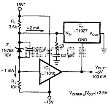
The described circuit employs an LT1027 integrated circuit (IC) to serve as a power buffer, which is essential for increasing the output current capability of a voltage reference. The role of the LT1027 is to maintain a stable 5 V output while isolating the load from the voltage reference source. This configuration is particularly beneficial in applications where the load may vary significantly, as it allows the reference voltage to remain unaffected by changes in the load current.
The RC damper, composed of a 50-ohm resistor and a 0.1 µF capacitor, is critical for ensuring the stability of the feedback loop. This damper mitigates potential oscillations that could arise due to feedback instabilities, particularly when driving capacitive loads. Oscillation can occur when using low equivalent series resistance (ESR) capacitors, which are common in ceramic and mylar types. To prevent such issues, the circuit design recommends the use of aluminum electrolytic or tantalum capacitors, which typically exhibit higher ESR values and thus contribute to improved stability in this application.
In summary, the circuit effectively enhances the output current capability of a reference voltage while ensuring reliability through overload protection and stability measures. Proper component selection, particularly regarding capacitors, is crucial for maintaining the desired performance and preventing oscillation. A method of boosting the output current of a reference and also protecting against overloads is shown in Fig. 66-5. IC1 acts as a power buffer. The LT1027 forces the output of V0ut and ground to be 5 V. The RC damper (50 and 0.1 Â¥) provides loop stability. The output might oscillate if low ESR capacitors are connected to it, so use aluminum electrolytic or tantalum capacitors instead of ceramic or mylar. 🔗 External reference
Related Circuits
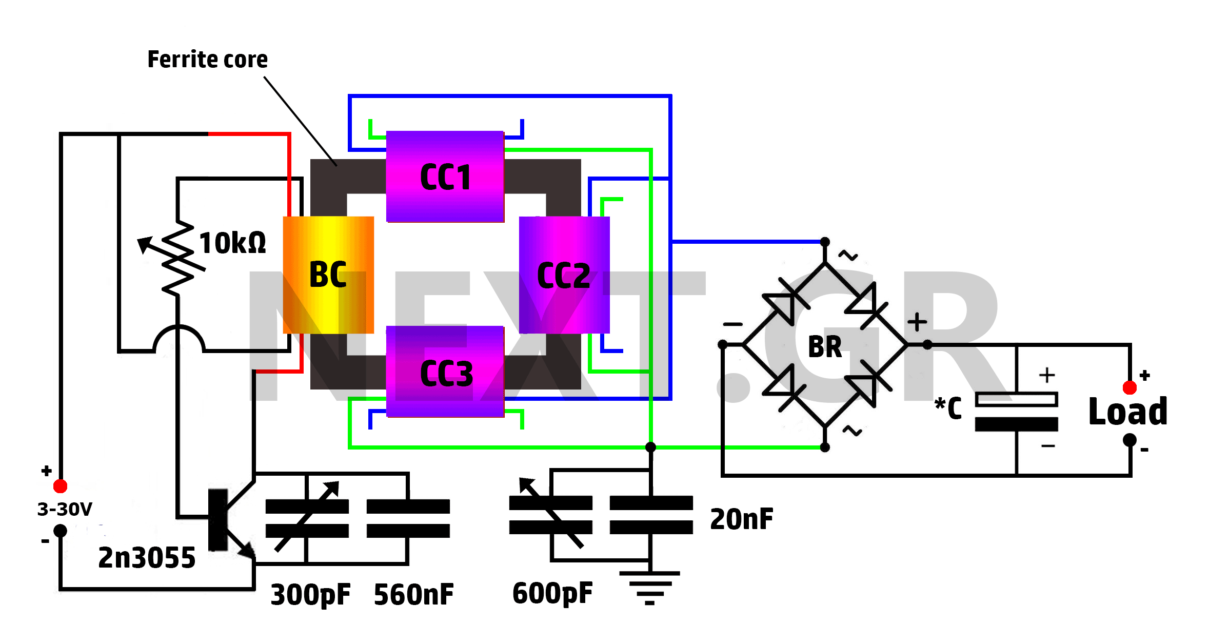
This is a Tesla/joule thief hybrid circuit that its inventor claims can produce 90 times the input power. The circuit can be self-looped and can provide 1050W of power, with only 11.6W looping back to supply the joule thief....
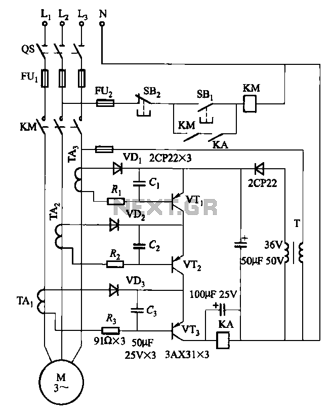
Drawing transistors that comprise the gate VTi, VT2, VT3, and similar components. The schematic involves a configuration of transistors designated as VTi, VT2, and VT3, which are integral to forming a gate structure. These transistors are typically arranged in a...
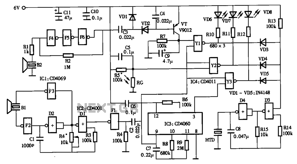
The timing circuit utilizes an electronic switch composed of F1, F2, and VT1 to reduce quiescent current to approximately 1 to 2 A with the 555 timer. Upon initial power-up, the voltage across capacitor C2 cannot instantly change, causing...
The primary amplifying stages consist of triode-connected 6088 tubes. As previously mentioned, there are two amplifying stages, which provide a non-inverted input to output connection and sufficient gain to include tone control. The tone controls are switch-selected, allowing a...
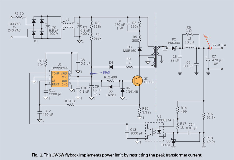
Through simple circuit modifications, designers can use peak current limiting to produce a constant current source. A constant current source is an essential component in various electronic applications, providing a steady output current regardless of load fluctuations or variations in...
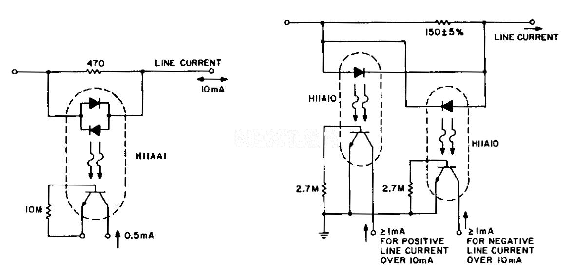
The detection of line-current flow and its indication at an electrically remote point is essential for line status monitoring in various telephone systems and auxiliary systems. The monitoring circuit must minimally unbalance or load the line, while also being...