
Low Power FM Transmitter
The low-power FM transmitter circuit is designed to enable sound transmission from various audio sources by modulating the frequency of an oscillator circuit. The transmitter operates within the commercial FM band, and careful attention must be given to selecting an appropriate, unused frequency to avoid interference with existing broadcasts. The circuit's efficiency relies on its ability to generate a stable RF signal, which can be verified using an RF probe, particularly beneficial for users lacking sophisticated oscilloscopes.
The circuit consists of several key components, including a Colpitts oscillator, which is responsible for generating the RF signal. The oscillator is tuned using a variable capacitor (C3), which must be adjusted to eliminate background noise. This adjustment should be performed while ensuring that the rotor of C3 is connected to a +9V power supply to minimize frequency disturbances during tuning. The inclusion of a capacitor from the base of the oscillator transistor (Q1) to ground enhances stability, allowing the circuit to operate effectively at RF frequencies.
The output from the oscillator is fed into a buffer and amplifier stage (Q2), which serves to isolate the antenna from the oscillator, thereby improving frequency stability and providing additional gain. The tuned collector load formed by L2 and C6 further optimizes performance, while C7 aids in preventing short circuits if the antenna contacts the grounded case.
The audio input, limited to approximately 100mV, is applied to the base of Q1, where it modulates the collector current, resulting in frequency modulation that can be received by standard FM receivers. The circuit's design also includes provisions for frequency response adjustment; for instance, C1 can be replaced with a larger capacitor to extend the lower frequency response as needed.
Inductors used in the circuit are constructed from enamelled copper wire, wound closely on a non-conductive former. Proper care must be taken to ensure that the enamel is removed at the contact points to ensure reliable electrical connections. The circuit utilizes specific capacitor types to maintain performance stability across varying temperatures, with recommendations for ceramic capacitors in most instances.
For enhanced audio quality, pre-emphasis can be integrated into the microphone preamp or line buffer circuit, which are designed to offer superior performance compared to standard configurations. The use of operational amplifiers, such as the TL071, provides improved distortion characteristics and predictable output impedance. The preamp should be housed in a shielded enclosure to prevent RF interference, ensuring optimal performance of the transmitter.
Overall, this low-power FM transmitter circuit design is suitable for hobbyists and engineers looking to explore RF transmission technology, while emphasizing the importance of proper assembly, tuning, and shielding to achieve the best results.I have had a few inquiries about a low power FM transmitter, and this article should satisfy those who might want to build one. It is designed to use an input from another sound source (such as a guitar or microphone), and transmits on the commercial FM band it is actually quite powerful, so make sure that you select an unused position on the
dial! NOTE: A few people have had trouble with this circuit. The biggest problem is not knowing if it is even oscillating, since the frequency is outside the range of most simple oscilloscopes. See Project 74 for a simple RF probe that will (or should) tell you that you have a useful signal at the antenna.
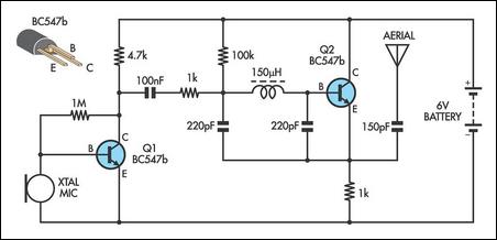
If so, then you know it oscillates, and just have to find out at what frequency. This may require the use of an RF frequency counter if you just cannot locate the FM band. The circuit of the transmitter is shown in Figure 1, and as you can see it is quite simple. The first stage is the oscillator, and is tuned with the variable capacitor. Select an unused frequency, and carefully adjust C3 until the background noise stops (you have to disable the FM receiver`s mute circuit to hear this). Because the trimmer cap is very sensitive, make the final frequency adjustment on the receiver. When assembling the circuit, make sure the rotor of C3 is connected to the +9V supply. This ensures that there will be minimal frequency disturbance when the screwdriver touches the adjustment shaft.
You can use a small piece of non copper-clad circuit board to make a screwdriver this will not alter the frequency. Note: A reader has suggested that the frequency stability is improved considerably by adding a capacitor from the base of Q1 to ground.
This ensures that the transistor operates in true common base at RF. A value of 1nF (ceramic) as shown is suitable, and will also limit the HF response to 15 kHz this is a benefit for a simple circuit like this. All capacitors must be ceramic (with the exception of C1, see below), with C2 and C6 preferably being N750 (Negative temperature coefficient, 750 parts per million per degree Celcius).
The others should be NPO types, since temperature correction is not needed (nor is it desirable). If you cannot get N750 caps, don`t worry too much, the frequency stability of the circuit is not that good anyway. Q1 is the oscillator, and is a conventional Colpitts design. L1 and C3 (in parallel with C2) tunes the circuit to the desired frequency, and the output (from the emitter of Q1) is fed to the buffer and amplifier Q2.
This isolates the antenna from the oscillator giving much better frequency stability, as well as providing considerable extra gain. L2 and C6 form a tuned collector load, and C7 helps to further isolate the circuit from the antenna, as well as preventing any possibility of short circuits should the antenna contact the grounded metal case that would normally be used for the complete transmitter.
The audio signal applied to the base of Q1 causes the frequency to change, as the transistor`s collector current is modulated by the audio. This provides the frequency modulation (FM) that can be received on any standard FM band receiver. The audio input must be kept to a maximum of about 100mV, although this will vary somewhat from one unit to the next.
With the value shown for C1, this limits the lower frequency response to about 50Hz (based only on R1, which is somewhat pessimistic) if you need to go lower than this, then use a 1uF cap instead, which will allow a response down to at least 15Hz. C1 may be polyester or mylar, or a 1uF electrolytic may be used, either bipolar or polarised. If polarised, the positive terminal must connect to the 10k resistor. The inductors are nominally 10 turns (actually 9. 5) of 1mm diameter enamelled copper wire. They are close wound on a 3mm diameter former, which is removed after the coils are wound. Carefully scrape away the enamel where the coil ends will go through the board all the enamel must be removed to ensure good contact.
Figure 2 shows a detail drawing of a coil. The coils should be mounted about 2mm above the board. For those still stuck in the dark ages with imperial measurements (grin), 1mm is about 0. 04 ³ (0. 0394 ³) or 5/127 inch (chuckle) you will have to work out what gauge that is, depending on which wire gauge system you use (there are several). You can see the benefits of metric already, can`t you To work out the other measurements, 1 ³ = 25. 4mm It is normal with FM transmission that pre-emphasis is used, and there is a corresponding amount of de-emphasis at the receiver.
There are two standards (of course) most of the world uses a 50us time constant, and the US uses 75us. These time constants represent a frequency of 3183Hz and 2122Hz respectively. This is the 3dB point of a simple filter that boosts the high frequencies on transmission and cuts the same highs again on reception, restoring the frequency response to normal, and reducing noise.
The simple transmitter above does not have this built in, so it can be added to the microphone preamp or line stage buffer circuit. These are both shown in Figure 3, and are of much higher quality than the standard offerings in most other designs.
Rather than a simple single transistor amp, using a TL071 opamp gives much better distortion figures, and a more predictable output impedance to the transmitter. If you want to use a dynamic microphone, leave out R1 (5. 6k) since this is only needed to power an electret mic insert. The gain control (for either circuit) can be an internal preset, or a normal pot to allow adjustment to the maximum level without distortion with different signal sources.
The 100nF bypass capacitors must be ceramic types, because of the frequency. The mic preamp has a maximum gain of 22, giving a microphone sensitivity of around 5mV. The line preamp has a gain of unity, so maximum input sensitivity is 100mV. Select the appropriate capacitor value for pre-emphasis as shown in Figure 3 depending on where you live. The pre-emphasis is not especially accurate, but will be quite good enough for the sorts of uses that a low power FM transmitter will be put to.
Needless to say, this does not include bugging of rooms, as this is illegal almost everywhere. I would advise that the preamp be in its own small sub-enclosure to prevent RF from entering the opamp input. This does not need to be anything fancy, and you could even just wrap some insulation around the preamp then just wrap the entire preamp unit in aluminium foil.
Remember to make a good earth connection to the foil, or the shielding will serve no purpose. 🔗 External reference
Related Circuits
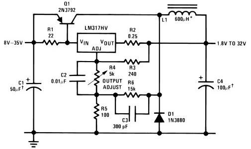
The circuit diagram of this LM317 power supply electronic project requires a few external components. The input voltage for this project must be between 8 and 35 volts, providing a variable output voltage ranging from 1.8 volts to 32...
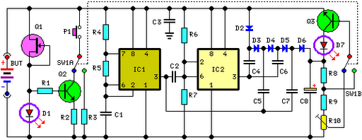
FET Q1 functions as a constant current generator, providing biasing for LED D1 and the base of Q2. This configuration ensures that D1 emits light at a consistent intensity, regardless of the battery voltage, which ranges from 3 to...
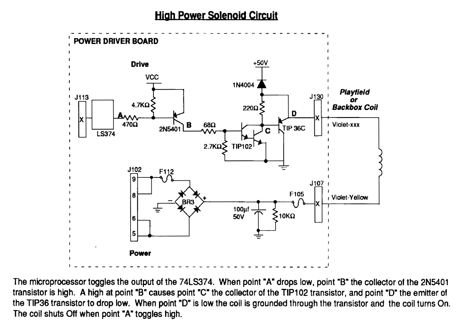
Instructions for using an LED-Wiz to control pinball solenoids. Rottendog Amusements manufactures modern replacement driver boards, such as the Williams WPC89/WPC-S replacement. Although this board is an improvement over the originals, it remains relatively large and is capable of...
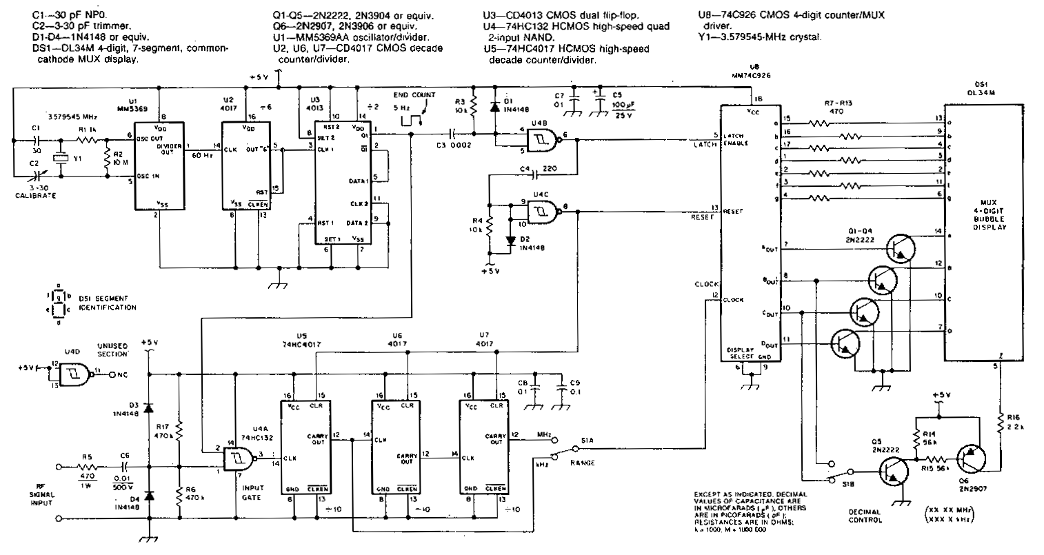
This counter features a four-digit display that can be switched to display frequencies ranging from 1 to 40 MHz, with a resolution of 100 Hz. The MM74C926 CMOS IC serves as the four-digit decimal counter, which can latch a...
This AM transmitter design is notably simple to construct due to its use of a non-tapped inductor featuring a single winding. The inductor can be conveniently sourced as a standard RF choke, such as the Jaycar Cat LF-1536. To...
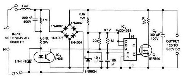
Universal power supply with a safe high-voltage capacitor power supply. Refer to that page to read the explanation about the related circuit diagram of the above power supply. The universal power supply circuit is designed to provide a stable output...