
Self-Powered Fast Battery Tester Schematic
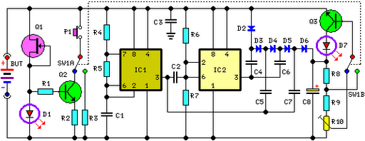
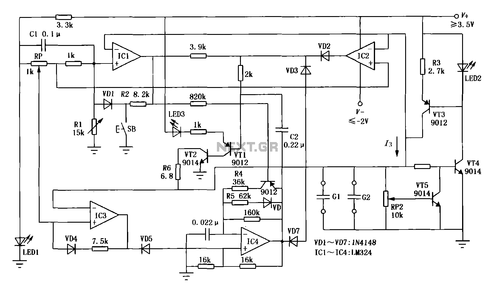
FET Q1 plays a critical role in regulating the current supplied to LED D1 and Q2's base. The constant current generator design ensures that the LED maintains a steady brightness, which is essential for visual feedback during testing. The operational range of the circuit, accommodating battery voltages from 3V to 15V, allows for versatility in assessing various battery types.
IC1's function as a square wave generator is fundamental to the circuit's operation. The oscillation at approximately 3KHz enables the subsequent voltage multiplication process. IC2's role as an inverter complements IC1, allowing for the effective driving of diodes D2-D6 and capacitors C4-C7 in a manner that enhances voltage levels through a capacitive charge and discharge cycle.
The voltage divider formed by resistors R8-R10 is crucial for setting the biasing conditions for Q3. When P1 is not engaged, the circuit minimizes load on the battery under test, ensuring accurate voltage readings without significant drain. The transition of Q3 to an on state, indicated by the illumination of LED D7, serves as a visual cue that the battery's voltage has fallen below acceptable levels, prompting further action or testing.
In scenarios involving 1.5V batteries, the circuit adapts by applying a higher load current, thus ensuring accurate testing even at lower voltage levels. The inclusion of switches SW1A and SW1B provides user control over the load conditions and biasing of Q3, enhancing the circuit's functionality and adaptability for different battery types. Overall, this circuit design presents a robust solution for battery testing, combining constant current generation, voltage multiplication, and conditional loading to deliver reliable performance across a range of battery voltages.FET Q1 provides a constant current generator biasing LED D1 and Q2 Base. In this manner D1 illuminates at a constant intensity, independent of battery voltage from 3 to 15V and Q2 (when P1 is closed) applies a constant current load of about 120mA to the battery. IC1 is a square wave generator oscillating at about 3KHz. IC2 acts as an inverter and drives, together with IC1 but in anti-phase, Diodes D2-D6 and Capacitors C4-C7, obtaining a voltage multiplication. C8 is charged by this raised voltage and R8-R10 form a voltage divider biasing the Base of Q3. When P1 is open, a very light load is applied to the battery under test and Q3 Base is biased in order to maintain LED D7 in the off state.
Closing P1, a 120mA load is applied to the battery under test. If the battery is not fully charged, its output voltage starts reducing: when this voltage fall 0. 6V below the battery nominal voltage, Q3 Emitter becomes more negative than the Base, the transistor is hard biased and D7 illuminates. Obviously, this state of affairs will last a few seconds: the time spent by C8 to reduce its initial voltage to the new one, proportional to the voltage of the loaded battery.
If the battery under test is in a good charging state, its output voltage will not fall under a 120mA loading current, so LED D7 will stay off. When testing 1. 5V batteries, the circuit formed by Q1, Q2, D1, and R1 & R2 does not work well at this supply voltage, so a 150mA load current is applied to the BUT by means of the 10 Ohm resistor R3 after switching SW1A.
Q3 bias is also changed via SW1B. 🔗 External reference
Related Circuits
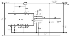
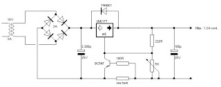
The circuit illustrates a TL494 pulse width modulated step-down converter schematic. This circuit allows for testing of line regulation, load regulation, output ripple, short circuit current, and efficiency under various input voltage conditions. A detailed table of these tests...
Many individuals find that they sleep well in natural environments, such as tents or wooden huts. This phenomenon is attributed not only to the healthy surroundings but also to our subconscious ability to perceive the Earth's natural magnetic fields....
A straightforward smoke detector circuit has been presented through a schematic diagram, which can be easily constructed and installed in an area for essential detection purposes. The circuit utilizes the versatile FIGARO TGS 813 gas sensor as the primary...
This circuit diagram represents a resource replacement for 1.3V mercury cells or other small batteries. It has various applications, including use in computers to activate a front panel multi-adapter equipped with a digital thermometer. The circuit draws power from...
The first circuit is designed for discharging nickel-cadmium batteries before recharging to eliminate the "memory effect." After discharging, the power is automatically converted to the state of charge. The charging process utilizes pulse-width modulation for constant current, along with...
The battery charger circuit described is straightforward to assemble, requiring only a few inexpensive components and an additional winding on the power transformer (or a separate transformer). Since this charger operates independently of sound reproduction, there are no stringent...
Warning: include(partials/cookie-banner.php): Failed to open stream: Permission denied in /var/www/html/nextgr/view-circuit.php on line 713
Warning: include(): Failed opening 'partials/cookie-banner.php' for inclusion (include_path='.:/usr/share/php') in /var/www/html/nextgr/view-circuit.php on line 713