
low power simple energy efficient circuit to make single IR LED blink
The proposed circuit design focuses on maximizing battery efficiency while achieving the desired LED blinking functionality. The use of a CR2032 battery, which has a nominal voltage of 3V, sets the constraints for the circuit components. The 555 timer, while a popular choice for timing applications, is not ideal due to its relatively high current draw, which can quickly deplete the battery. Instead, the CMOS 7555 variant is recommended as it operates at lower current levels, making it more suitable for battery-powered applications.
In terms of circuit configuration, the 7555 timer can be set up in astable mode to create a continuous square wave output that drives the LED. The frequency of blinking can be adjusted by selecting appropriate resistor and capacitor values in the timing network. The addition of a transistor can be implemented to handle the higher current requirements of the LED, ensuring that the timer's output does not exceed its rated capacity.
For applications requiring precise control over blinking patterns and duty cycles, the Bowin M34-2H presents a versatile solution. Its ability to be programmed for various blinking sequences allows for customization based on user preferences. The single resistor used to set the LED drive current can be selected to optimize brightness while maintaining battery life.
The NXP part offers advanced features such as variable cycle time and the ability to reduce the duty cycle significantly, which is crucial for extending battery life. It is particularly useful in scenarios where the LED needs to operate intermittently rather than continuously.
The NTE876 LED flasher/oscillator serves as another effective solution, providing a straightforward implementation with minimal external components. Its low operating current and the ability to drive the LED at 45 mA make it a strong candidate for applications requiring moderate brightness without compromising battery longevity.
In summary, the circuit design for powering an LED with a CR2032 battery can be effectively achieved using low-power components such as the 7555 timer, Bowin M34-2H, or NTE876 oscillator, each offering distinct advantages in terms of efficiency, programmability, and current handling capabilities. The selection of components should be based on the specific requirements of the application, including desired blink rates and LED brightness.Powering the LED with a 3V CR2032 battery and hoping I could extend the battery life by making the LED blink instead of having it on all the time. The 555 timer one, with large value resistors in the voltage divider, is probably the best. It might need an extra transistor to handle the 100ma. pjc50 Dec 17 `12 at 15:04 It might be useful to know how often do you need your led to blink, and how long
should it stay on. And you might wand to add further details about your specific project. Vladimir Cravero Dec 17 `12 at 16:15 555`s operating current is too large to be powered by a CR2023. If you really want to use a 555, instead use 7555, a CMOS variant of 555 timer. Chetan Bhargava Jan 6 `13 at 23:42 The comment above is right. "555" and "energy efficient" are like a fist and a face. When they meet, nothing good happens. Jonny B Good Jan 7 `13 at 11:09 You guys should probably take this to chat or form it into an answer. long comment chains are usually discouraged because it makes it hard for future readers to glean the actual answer.
Toby Lawrence Jan 8 `13 at 16:53 As several of the answers so far have dispensed with the 100 mA LED drive current requirement, limiting it instead to the 20 to perhaps 50 mA that typical microcontrollers will safely sink or source, here are some minimal, high efficiency solutions within the same current constraints. Bowin M34-2H is a 3-pin part that will flash an LED at 2 Hz with 25 mA current. It contains an internal RC oscillator, with +/- 20% tolerance, hence not terribly precise. The pin-out and application circuit from the datasheet: This 8-pin TSSOP part can be "trained" with a sequence of up to 3 blinking elements, and will then continue to blink as trained.
The programming connection can be removed after training, and this programming is achieved via a single signal line from any standard microcontroller, using the 1-Wire protocol. The single resistor in the schematic sets the LED drive current, between 1 mA and 20 mA. It itself does not carry significant current (less than 1 A), so will not drain the battery noticeably.
Given the choice, the NXP part would be a recommendation, both because it is from a major manufacturer, and because the blink pattern can be optimized down to 1/1024 duty cycle if needed, and cycle time varied across a wide range, covering the OP`s entire blink-rate range of interest. Lower the duty cycle, longer the battery will last. NTE876 LED flasher / oscillator operates from 1. 15 to 6 Volts, delivers up to 2 Volts to the connected LED at up to 45 mA, and needs an operating current of merely 0.
75 mA maximum. This is an 8-pin DIP IC, though SMD equivalents are available too. It just needs one external capacitor for timing adjustment, the R of the RC oscillator is internal. The 45 mA LED drive current brings this closer to the current goal stated in the question. 🔗 External reference
Related Circuits
WARNING: Do not touch any part of the circuit when it is running (connected to the power line); this circuit is not isolated from the mains supply. This circuit operates directly connected to the mains supply, which poses a significant...
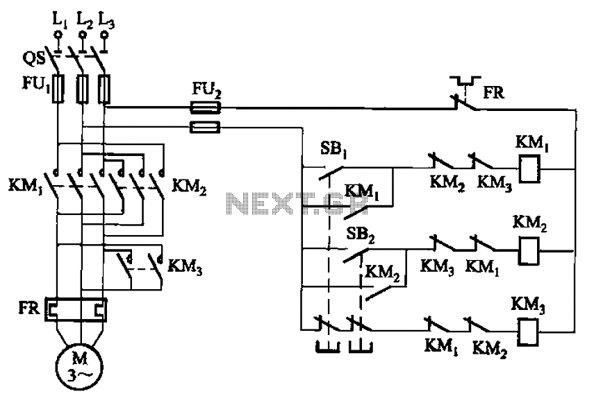
The circuit depicted in Figure 3-154 illustrates the KM3 braking contactors. During shutdown, the system can disconnect the operating system. At this point, KM3 activates, causing its normally open contact to close, thereby shorting the three-phase stator windings to...
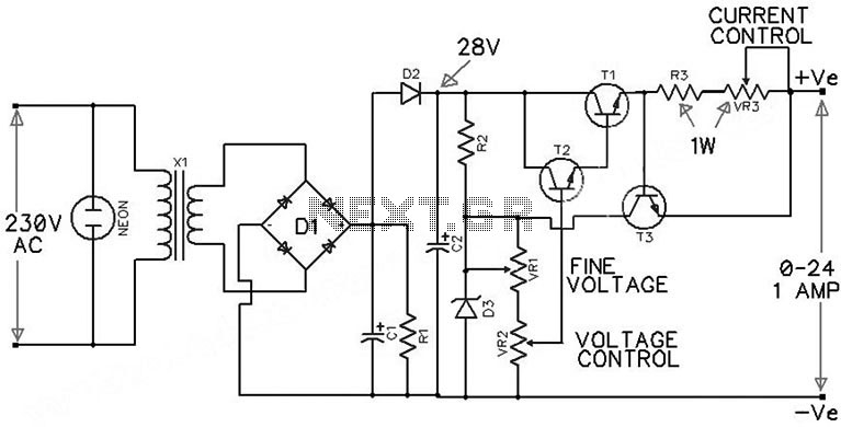
The circuit presented is an economical smooth variable power supply that provides an output range of 0V to 24V. It incorporates all necessary controls and short circuit protection while maintaining acceptable regulation and a ripple-free output, utilizing a minimal...
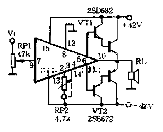
The AP500A amplifier offers numerous advantages, providing unmatched superiority in stereo applications. It can utilize various amplifier configurations, including OTI, CI, rK, BTL, class AB, and super CP. The typical DC amplifier module for the AP500A is illustrated in...
A simple test circuit designed for troubleshooting audio and radio equipment. It can inject a square wave signal rich in harmonics or be used with headphones as an audio tracer. A single-pole double-throw switch is utilized to toggle between...

A field strength meter utilizing a biased Schottky detector employs a temperature-compensated Schottky diode within an amplified, untuned field strength indicator powered by two AA cells. This device indicates the relative field strength of RF fields ranging from a...