
Detector switch circuits

This circuit serves as a versatile tool for audio and radio diagnostics, allowing users to efficiently identify faults in various equipment. The use of a single-pole double-throw switch facilitates easy mode switching between signal injection and audio tracing, enhancing usability. In the tracing mode, the circuit functions as a high-gain audio probe, with the earpiece connected to the collector of the final transistor, which is configured as an emitter follower. This configuration ensures that the output signal maintains a high level of fidelity and strength, crucial for accurate audio analysis.
The inclusion of a 1nF capacitor at the probe end effectively blocks any DC components from the signal, ensuring that only AC signals are processed. This is particularly important in audio applications where DC offsets can lead to distortion or damage to subsequent stages. The capacitive coupling between the two transistor stages allows for seamless signal transfer while maintaining the integrity of the audio frequencies being analyzed.
In the injection mode, when the switch is set to the position marked by the blue dot, the transistors are configured as an astable multivibrator. This configuration generates a square wave output that is rich in harmonics, making it ideal for testing the response of AM radio receivers. The frequency of the generated square wave can be adjusted to cover a wide range of audio frequencies, which is essential for comprehensive testing of radio equipment. The ability to produce signals up to several hundred kilohertz allows for thorough examination of the receiver's performance across various frequency ranges, ensuring that any potential issues can be effectively identified and addressed.
Overall, this simple yet effective circuit design provides essential functionalities for audio and radio equipment troubleshooting, making it a valuable tool for engineers and technicians in the field.A simple test circuit to fault find audio and radio equipment. Can be used to inject a square wave signal, rich in harmonics, or used with headphones as an audio tracer. A single pole double throw sitch is used to switch between inject and trace modes. The diagram is drawn in trace mode, the earpiece being connected to the collector of thelast tra nsistor. Both transistors are wired as emitter followers, providing high gain. DC blocking is provided by the 1n capacitor at the probe end, and the two stages are capacitively coupled. when the switch is thrown the opposite way (to the blue dot) both transistors are wired as an astable square wave generator.
This provides enough harmonics from audio up to several hundred kilohertz and is useful for testing AM radio Receivers. 🔗 External reference
Related Circuits

An ionization chamber in conjunction with a high-impedance CA3130 operational amplifier is utilized to detect the presence of smoke. When smoke is detected, the CA3130 ceases oscillation, which in turn triggers the S106D silicon-controlled rectifier (SCR) to sound an...

This is an intriguing 555 timer circuit designed to entertain and engage individuals while studying electronics in educational settings. Commonly referred to as a clap switch circuit, it operates as a sound-controlled flip-flop. This sound-controlled light can also function...
Similar to a field strength meter, an RF detector circuit serves as a valuable project for detecting nearby RF signals. The circuit presented here is capable of detecting a wide range of RF frequencies and provides an alarm when...
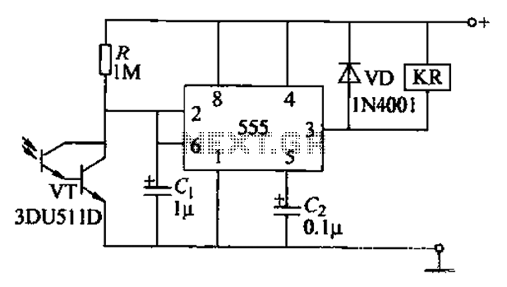
The circuit utilizes a Darlington-type phototransistor as the sensing element, which enhances sensitivity to low light levels, making it suitable for detecting reflected light signals. When the Darlington phototransistor is exposed to light, its resistance decreases, causing the voltage...

The project demonstration has been successfully completed, with the only remaining task being the final project report due on June 15, which will be integrated with a conference paper. This update marks the last entry in the electronic notebook,...

The following circuit is a power amplifier circuit for an FM transmitter with an output power of 30 watts. The power amplifier circuit utilizes a power transistor of type 2SC1946A. The FM transmitter operates with a 13.8-volt DC power...