
low voltage cutout for 12v sla
This circuit provides an effective solution for preventing over-discharge of SLA batteries, which can lead to reduced battery life and performance. The voltage divider configuration ensures that the battery voltage is accurately monitored, allowing for precise control over the load disconnection process. The use of an operational amplifier enables a fast response to voltage changes, ensuring that the load is disconnected promptly when the battery voltage falls below the set threshold.
The choice of components, such as the specific values of the resistors in the voltage divider and the characteristics of the MOSFET, is critical for optimizing the performance of the circuit. The 22kΩ and 20kΩ resistors can be adjusted to fine-tune the voltage threshold at which the load is disconnected, accommodating different battery specifications and application requirements.
Furthermore, the inclusion of a zener diode for reference voltage stabilization is essential, as it provides a consistent reference point for the operational amplifier, enhancing the reliability of the circuit. The transistor (Q1) functions as a switch that further reinforces the latching mechanism of the circuit, ensuring that once the load is disconnected, it remains in that state until manually reset.
For applications that require higher current loads, the selection of the MOSFET (Q2) should be based on its current rating and R_DS(on) value, ensuring minimal energy loss during operation. If a relay is used instead of a MOSFET, careful consideration must be given to the relay's coil voltage and current ratings, and the diode across the coil must be rated to handle the back-EMF generated when the relay is de-energized.
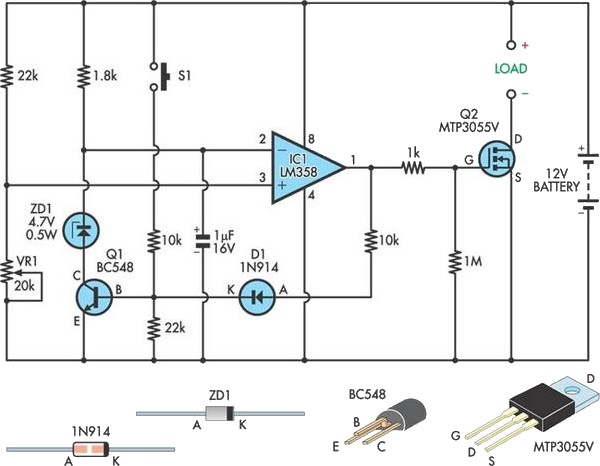
Overall, this circuit design is a practical solution for battery management, ensuring the longevity and reliability of SLA batteries in various applications.This simple circuit protects an SLA battery from over-discharge by disconnecting the load when the terminal voltage drops below a preset level. In operation, a sample of the battery voltage is derived from the 22k © resistor and 20k © trimpot divider.
This is applied to the non-inverting input (pin 3) of IC1, where it is compared with a reference voltage on the inverting input (pin 2). When the sampled battery voltage falls below the reference voltage, IC1`s output (pin 1) swings towards ground, switching Mosfet Q2 off and disconnecting the load from the battery. The reference voltage is derived from a 4. 7V zener diode (ZD1), which is connected to ground via the collector-emitter circuit of Q1 (ie, when Q1 is on).
However, when the op amp`s output is driven low, Q1 is switched off, causing the non-inverting input to rise towards the full battery voltage. This greatly reinforces the switching action, latching the circuit in the "off" state until the battery is recharged and the reset switch (S1) pressed.
The Mosfet used for Q2 should be selected to suit the intended application. The circuit could also drive a relay simply by connecting the coil across the "load" terminals. As is usual practice, a diode should be connected across the relay coil to limit back-EMF spikes. 🔗 External reference
Related Circuits
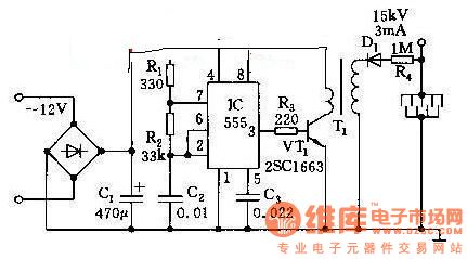
This high voltage generator is capable of producing a stable high voltage exceeding 8kV. The circuit design is straightforward, ensuring stability and reliability. It consists of a step-down rectifier, a voltage regulator circuit, an 18kHz multivibrator-type oscillator, and a...
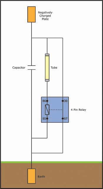
An individual has been studying Nikola Tesla's work for approximately 11 months and recently discovered Imhotep's concept of Radiant energy. The study of Nikola Tesla's contributions to electrical engineering and energy transmission has led to significant advancements in understanding electromagnetic...

This device triggers the slave flash simultaneously with the main flash. Certain flash settings on digital SLR cameras may not be compatible. It offers an extended battery life, capable of up to 300 hours of use or more. If...
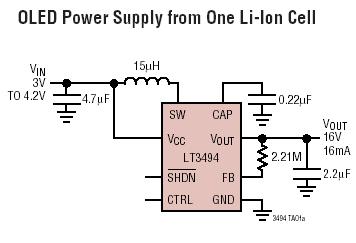
The LT3494 and LT3494A are low-noise boost converters that integrate a power switch, Schottky diode, and output disconnect circuitry. These devices utilize an innovative control technique that results in minimal output voltage ripple and high efficiency across a broad...
The circuit diagram was designed to create a power supply without utilizing any transformer circuit. This circuit illustrates the advantages as well as the limitations of transformerless power supplies. The transformerless power supply circuit typically employs a capacitive dropper method...
A schematic representation of the SASS 2400 is shown in Figure 2 below. The cyclone has four main sections: a cyclonic cup, stripping column, cistern, and water feedback loop. A high-efficiency, brushless centrifugal blower at the cyclone exit pulls...