
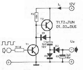
Low voltage flasher
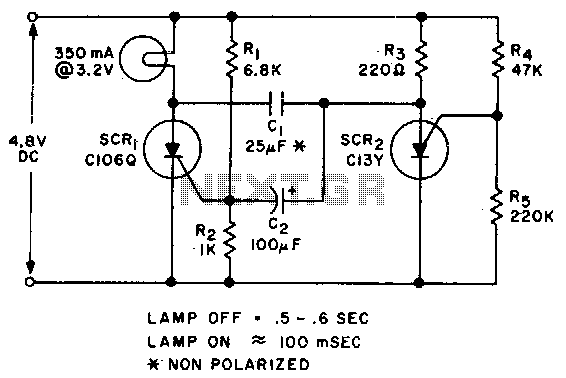
The described circuit utilizes two silicon-controlled rectifiers (SCRs) in a configuration that allows for controlled triggering and commutation. When a voltage is applied, SCR1 becomes conductive, allowing current to flow through it. This action raises the voltage at the anode of SCR2, which is connected in a manner that it remains off until the appropriate voltage is reached. Once the voltage at the anode of SCR2 exceeds its triggering threshold, SCR2 conducts, effectively providing a path for current that can turn off SCR1.
The behavior of SCR1 is influenced by the voltage at its gate. During the operation, when SCR1 is triggered, the gate voltage experiences a negative swing due to the feedback from SCR2. This negative swing is critical for the commutation process, as it helps to turn off SCR1. However, it is essential to ensure that this negative voltage does not exceed -6 volts, as exceeding this limit could lead to damage or malfunction of SCR1.
For applications requiring higher voltage levels, careful consideration must be given to the voltage ratings of both SCRs and the components surrounding them. The design must ensure that the SCRs can handle the maximum expected voltage and current levels without exceeding their specified limits. Additionally, appropriate protective measures, such as snubber circuits or voltage clamps, may be implemented to safeguard against transient voltages that could occur during operation.
This circuit configuration is widely applicable in power control systems, motor drives, and other applications where controlled switching of high voltages is necessary. Proper thermal management and heat dissipation strategies should also be considered to enhance the reliability and longevity of the SCRs in the circuit.Applying voltage to the circuit triggers SCR1. With SCRl on, the voltage on the anode of SCR2 rises until SCR2 triggers to commu-tate SCRl. The voltage on the gate of SCRl will swing negative at this time, and only after a positive potential of 0 volt is once again attained, will SCRl retrigger The circuit could be used for higher voltage levels, but the peak negative voltage on the gate of SCRl must be limited to less than 6 volts. 🔗 External reference
Related Circuits
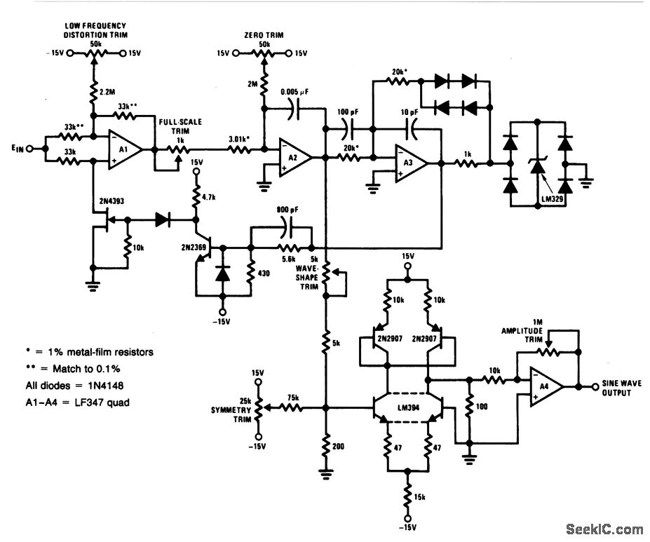
For a 0- to 10-V input, this circuit generates sine-wave outputs ranging from 1 Hz to 20 kHz, achieving linearity better than 0.2%. The distortion level is approximately 0.4%, and both the frequency and amplitude of the sine-wave output...
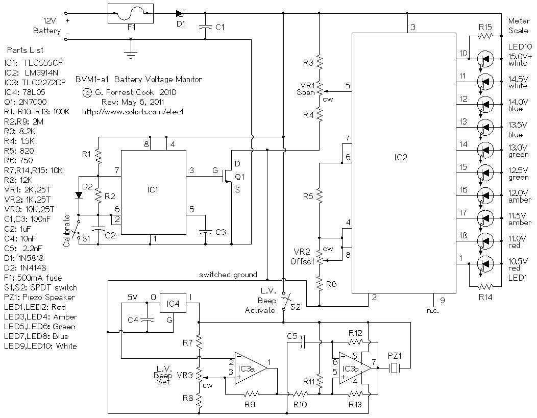
This circuit provides an audible and visual low voltage warning for 12V battery powered devices. When the battery voltage is above the set point (typically 11V), the circuit is idle. If the battery voltage should fall below the set...
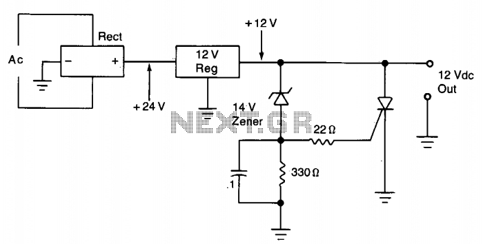
The silicon controlled rectifier (SCR) is designed to handle at least the current provided by the power supply. It is connected in parallel across the 12 V DC output lines but remains inactive until a voltage is applied to...
The schematic below illustrates a simple LED flasher circuit. This circuit utilizes three LEDs that begin to blink or flash upon receiving a 9-volt supply. It is straightforward in design, employing a self-flashing LED (LED 1) to trigger the...
Voltage inverter circuit design electronic project using few electronic components The voltage inverter circuit is a fundamental electronic project that converts direct current (DC) to alternating current (AC). This circuit is particularly useful in applications where AC voltage is required...
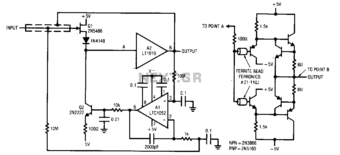
Q1 and Q2 form a simple, high-speed FET input buffer. Q1 operates as a source follower, while Q2 serves as a current-source load that regulates the drain-source channel current. The LT1010 buffer is utilized to provide output drive capability...