
Overvoltage protection circuit

The silicon controlled rectifier (SCR) is a semiconductor device that serves as a switch, allowing current to flow in one direction once it is triggered. In this configuration, the SCR is utilized for overcurrent protection in a power supply circuit. The SCR is placed in parallel with the output lines, which means that it monitors the output voltage across the load.
The zener diode plays a critical role in the triggering mechanism. It is connected in such a way that it only begins to conduct when the voltage across it exceeds 14 V. This characteristic is essential for ensuring that the SCR remains off during normal operating conditions, thereby preventing inadvertent activation. The 330-ohm resistor is used to limit the current flowing into the gate of the SCR, ensuring that the SCR receives just enough triggering current to turn on without exceeding its specifications.
When the input voltage rises above 14 V, the zener diode conducts, creating a voltage drop across the 330-ohm resistor. This voltage drop generates a gate current sufficient to trigger the SCR into conduction. Once triggered, the SCR enters its "on" state, which effectively connects the output lines of the power supply directly to ground. This action creates a short circuit condition, which can lead to excessive current flow.
The protective measure in this configuration is the primary fuse, which is designed to blow when excessive current is detected. If a fuse is present, it will interrupt the circuit, preventing damage to the transformer and other components. However, if there is no fuse, the transformer may overheat and sustain damage due to the excessive current passing through it, potentially leading to catastrophic failure.
In summary, the SCR and zener diode configuration serves as an effective overcurrent protection mechanism in a DC power supply. The careful selection of the zener voltage and the value of the resistor is crucial for ensuring reliable operation and protection of the circuit components.The silicon controlled rectifier (SCR) is rated to handle at least the current of the power supply. It is connected in parallel across the 12 V dc output lines, but remains inert until a voltage appears at the gate terminal. This triggering voltage is supplied by the zener diode. At potentials less than 14 V the zener will not conduct current. But, at potentials greater than 14 Vdc the zener conducts and creates a voltage drop across the 330 ohm resistor that will fire the SCR.
When the SCR turns on, the output lines of the power supply are shorted to ground. This will blow the primary fuse or burn out the transformer if there is no primary fuse.
Related Circuits
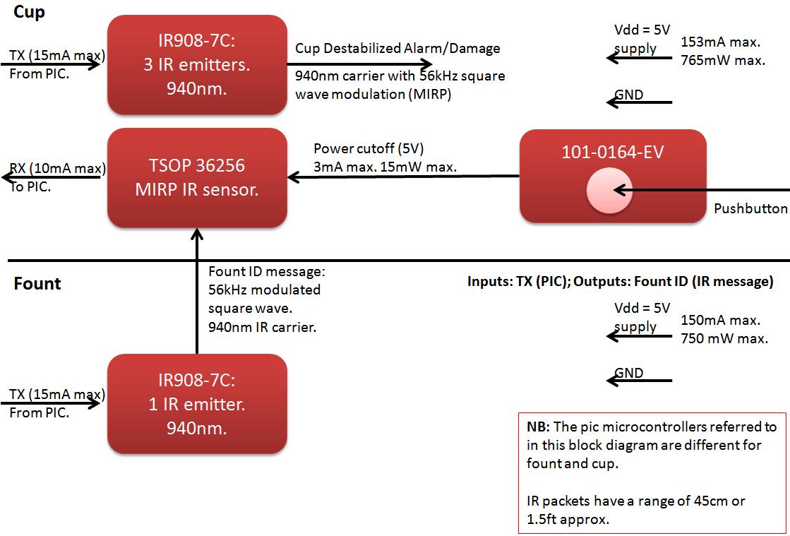
The founts must notify the server when the cup is taken from the fount or when the opponent's cup is poured into the team's cup. The implementation of the actual pouring action is at the discretion of the team....
This device is a simple timer that keeps the headlights of a vehicle on for approximately 1 minute and 30 seconds, allowing for illumination when accessing dark areas without the need to return to switch off the lights. Pressing...
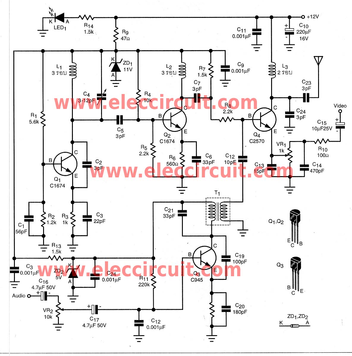
To transmit video and audio signals to multiple televisions simultaneously, a video amplifier splitter utilizing a transistor can be employed. A video amplifier splitter is an electronic device designed to distribute a single video and audio signal to multiple output...
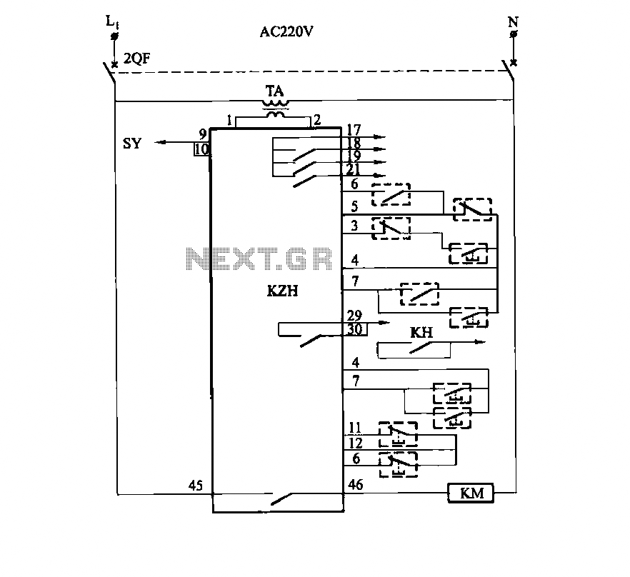
It utilizes the SHD series of electronic control equipment modules. The fan control box KZH functions as the HKD 1F electronic module. The SHD series of electronic control equipment is designed for various applications, including fan control systems. Within this...
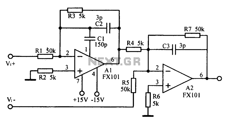
Common mode input voltage up to a difference of 100V enlarged circuit diagram. The circuit diagram described features a design capable of handling a common mode input voltage with a differential range of up to 100V. Such a configuration is...
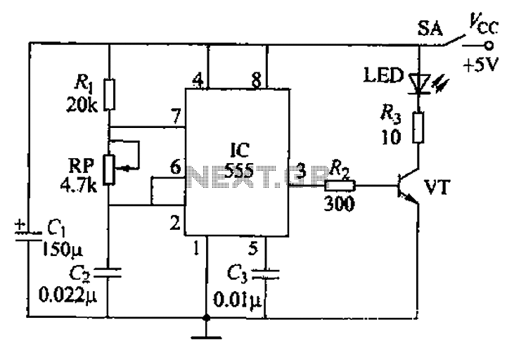
The circuit utilizes a 555 timer integrated circuit along with a transistor (VT) and several external components to create a multivibrator circuit. The charge and discharge time constants, Ti and T2, are defined, where Ti is approximately 0.7 times...