
Voltage controlled sine wave oscillator
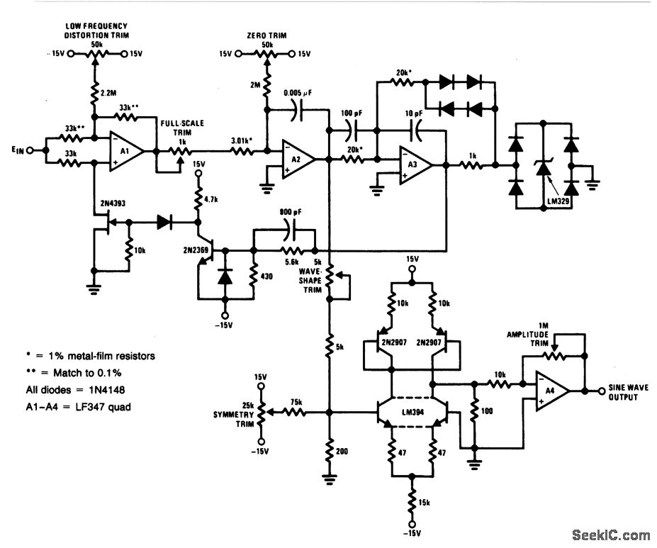
This circuit is designed to generate a precise sine-wave output based on a specified input voltage range of 0 to 10 V. The operational frequency range spans from 1 Hz to 20 kHz, making it suitable for various applications requiring accurate waveform generation. The circuit maintains linearity better than 0.2%, which is critical for applications where signal fidelity is paramount. The distortion level of approximately 0.4% indicates that the output waveform closely resembles an ideal sine wave, which is essential for audio and signal processing tasks.
The calibration procedure is integral to ensuring the circuit operates correctly. The first step involves applying a 10 V input, which serves as a reference point for the subsequent adjustments. The wave-shape trim and symmetry trim controls allow for fine-tuning of the output waveform to achieve minimal distortion. A distortion analyzer is employed to provide quantitative feedback during this calibration phase, ensuring that adjustments yield the desired results.
Following the initial calibration, the circuit is tested at a lower frequency of 10 Hz. This step is crucial for ensuring the circuit's performance at lower frequencies, which can often be more challenging due to increased distortion effects. The low-frequency distortion trim is adjusted to minimize any distortion detected at this frequency.
Finally, the zero and full-scale potentiometers are adjusted to establish a direct correlation between input voltage levels and output frequency. This ensures that a 500 V input results in a 1 Hz output, while a 10 V input produces a 20 kHz output. Such a calibration process not only verifies the circuit's accuracy but also enhances its reliability across the specified input range and frequency spectrum. The design and calibration of this circuit make it a versatile tool for signal generation in various electronic applications.For a 0- to 10-V input, this circuit produces sine-wave outputs of 1 Hz to 20 kHz, with better than 0. 2% linearity. Distortion is about 0. 4% and the sine-wave output frequency and amplitude settle instantaneously to a step-input change. To calibrate, apply 10 V to the input and adjust the wave-shape trim and symmetry trim for minimum distortion on
a distortion analyzer. Next, adjust the input voltage for an output frequency of 10 Hz and trim the low-frequency distortion for minimum indication on the distortion analyzer. Finally, alternately adjust the zero and full-scale pots so that inputs of 500 V and 10 V yield respective outputs of 1 Hz and 20 kHz.
🔗 External reference
Related Circuits
A capacitor in series with the crystal can be utilized to adjust the output frequency of the oscillator. The value can range between 20 pF and 0.01 µF, or it can be a trimmer capacitor. The values are approximate...
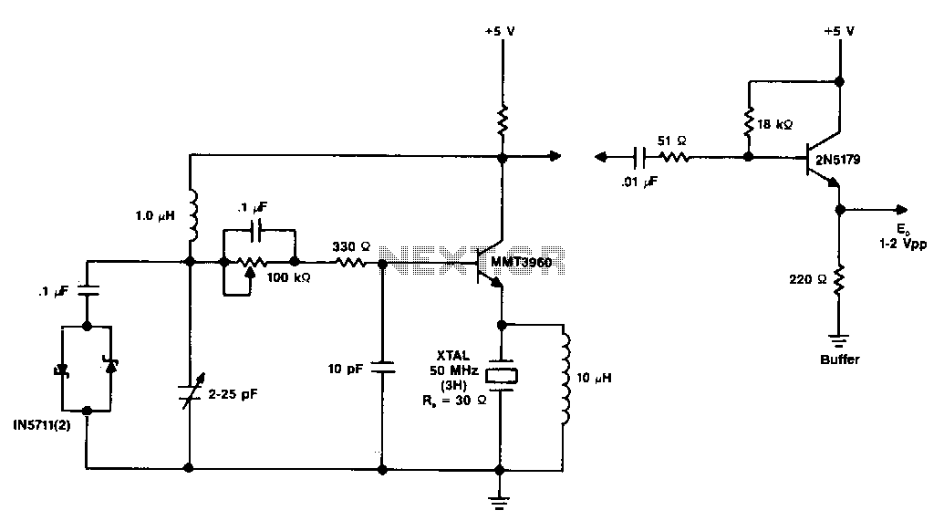
The diagram illustrates a 50 MHz oscillator functioning at its third harmonic. The collector load resistor R1 has been increased due to the rise in the quartz crystal's internal series resistance Rs, which escalates with frequency in the VHF...
A highly stable 60-Hz sine wave can be delivered with this circuit, which offers a different and much simpler approach to achieving a stable amplitude. Capacitor coupling in the last stage removes any DC component caused by unequal Zener...

When discussing fan control, there are generally two methods: linear control and pulse-width modulation (PWM) control. Linear control is the most commonly used method, which involves reducing the voltage supplied to the fan. For a fan rated at 12...
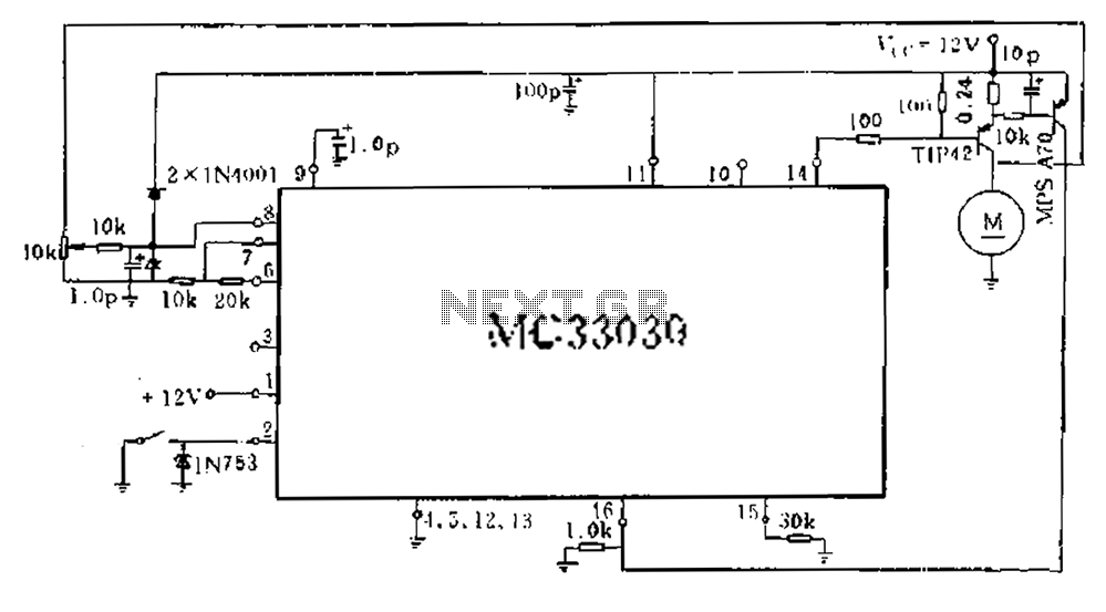
An alternative approach involves obtaining a motor's counter electromotive force from the motor end of the related signal after it has been amplified and averaged across three pins. The drive output A functions as a single-ended output, which controls...
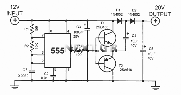
This DC voltage doubler circuit generates a voltage that is double the input supply voltage. It is beneficial when a higher voltage is required from a single lower voltage power source, particularly in applications with low current consumption. The DC...