
Low voltage lamp flasher

The described circuit effectively utilizes a relaxation oscillator and SCR flip-flop configuration to control the timing of a lamp's illumination. The relaxation oscillator, driven by Q1, generates a periodic waveform that charges capacitor C1 until it reaches a threshold voltage. This threshold is determined by the characteristics of the PUT, which serves as a switching device in the circuit.
When the PUT is triggered, it generates a pulse that is coupled through the two 0.02 µF capacitors to the gates of Q2 and Q3. The operation of Q2 and Q3 as an SCR flip-flop allows for the bistable switching of the output. Initially, when Q3 is in the conducting state, capacitor C4 is charged in a specific polarity. The subsequent pulse from the PUT oscillator turns Q2 on, which applies the voltage across C4 to Q3, effectively reverse-biasing it. This action causes Q3 to turn off, interrupting the current flow through the lamp.
After Q3 turns off, capacitor C4 discharges and then begins to charge again, but with its polarity reversed. This reversal is critical for the next cycle of operation. The next pulse from Q1 then turns Q3 on while simultaneously turning Q2 off, allowing the cycle to repeat. The use of a non-polarized capacitor (C4) is essential in this configuration, as it allows for the capacitor to be charged in both directions without risk of damage.
The timing characteristics of the circuit, specifically the duration for which the lamp remains on and off, are primarily determined by the values of the components used, particularly the timing capacitor C1 and the resistors in the circuit. With the specified values, the lamp operates in a duty cycle of approximately 1 second on and 1 second off, which can be adjusted by changing the component values to achieve different timing intervals. This circuit design is beneficial for applications requiring controlled illumination or signaling, such as in flashing lights or timing indicators.The circuit is composed of a relaxation oscillator formed by Q1 and an SCR flip-flop formed by Q2 and Q3. With the supply voltage applied to the circuit, the timing capacitor CI charges to the firing point of the PUT, 2 volts plus a diode drop.
The output of the PUT is coupled through two 0.02 ^F capacitors to the gate of Q2 and Q3. To clarify operation, assume that Q3 is on and capacitor C4 is charged plus to minus as shown in the figure. The next pulse from the PUT oscillator turns Q2 on. This places the voltage on C4 across Q3 which momentarily reverse biases Q3. This reverse voltage turns Q3 off. After discharging, C4then charges with its polarity reversed to that shown. The next pulse from Q1 turns Q3 on and Q2 off. Note that C4 is a non-polarized capacitor. For the component values shown, the lamp is on for about Vi second and off the same amount of time.
Related Circuits
This cost-effective circuit can be connected to an air conditioner, refrigerator, or any other advanced electrical appliance for protection. This circuit serves as a protective device for sensitive electrical appliances such as air conditioners and refrigerators. It is designed to...
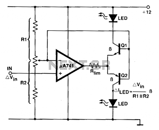
An operational amplifier (op amp) is utilized as a comparator and as a current sink for an LED. The output voltage of the amplifier varies by approximately 1.4 V based on the direction of the current. At any given...

Application of a kilowatt high-pressure mercury lamp ballast system; the schematic in Figure 12.44 illustrates the IR213D used for a high-pressure mercury lamp ballast system. The IR2130 is utilized not only to drive a single-phase full-bridge inverter with four...
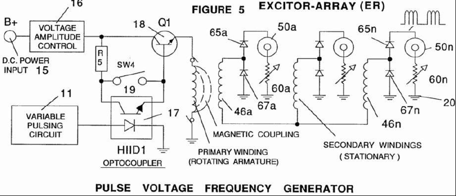
A power supply system utilizes a generator as a source of fuel to separate hydrogen and oxygen gases from natural water. It has the capability to control gas production by varying the amplitude of the voltage and/or the pulse...
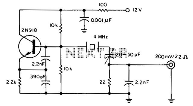
The oscillator provides an output with high spectral purity while maintaining the typical stability associated with crystal oscillators. The crystal not only sets the oscillator's frequency but also functions as a low-pass filter to eliminate unwanted harmonics and as...
It connects to the USB port and is ideal for checking motherboard switches and jumper settings. Many users may recall a commercial product from a few years ago, the "Itty Bitty Book Light," which was designed to clip onto...