
Low Voltage Microphone Preamplifier Circuit
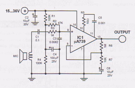
The low voltage microphone preamplifier circuit is designed to amplify audio signals from microphones with minimal distortion and noise. The use of a 1.5V power supply allows for compatibility with battery-operated devices, enhancing portability. The preamplifier stage, characterized by a 500 kHz unity-gain bandwidth, ensures that the circuit can effectively handle a wide range of audio frequencies, making it suitable for various applications, including voice recording and sound reinforcement.
The gain of 100 in the preamplifier stage significantly boosts the microphone signal, which is often weak. Following this stage, the output is adjusted using a gain-control potentiometer, allowing for fine-tuning of the signal level before it is sent to the op-amp. The op-amp is configured for a gain of 10, which further amplifies the signal to achieve a total gain of 60 dB. This level of amplification is adequate for most audio applications, providing a strong signal that can be processed by subsequent audio equipment without introducing significant noise.
The input impedance of 10 k ohms is designed to match the output of typical microphones, ensuring that the circuit does not load the microphone excessively, which could lead to signal degradation. Additionally, the design takes into account the potential for noise generation. While using the reference voltage as a preamplifier can introduce some noise, the low voltage helps to minimize this effect. The calculated input noise voltage of 440-500 nV/√Hz is a critical specification, indicating that the circuit is capable of maintaining a high signal-to-noise ratio, which is essential for high-fidelity audio applications.
This microphone preamplifier circuit represents a practical solution for low-voltage audio amplification needs, combining efficiency and performance in a compact design.This is a low voltage microphone preamplifier circuit with a 1. 5V power supply. The reference, with a 500 kHz unity-gain bandwidth, is used as a preamplifier with a gain of 100. Its output is fed through a gain-control potentiometer to the op amp, which is connected for a gain of 10. The combination gives a 60 dB gain with a 10 kHz bandwidth, unlo aded, and 5 kHz loaded at 500 ©. Input impedance is 10 k ©. Potentially, using the reference as a preamplifier in this fashion can cause excess noise. However, because the reference voltage is low, the nose contribution, which adds root-mean-square, is likewise low. The input noise voltage in this connection is 440-500 nV Hz, about equal to that of the amp. 🔗 External reference
Related Circuits
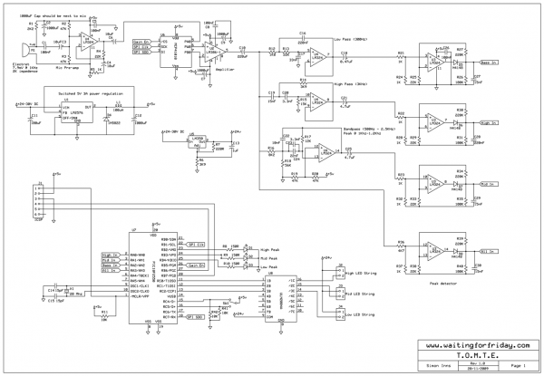
Most existing designs utilize direct switching of lights without any software control and include manual potentiometers for light sensitivity and overall gain settings. There are limited references regarding the frequency filter circuitry, explaining the specific frequencies the circuit is...
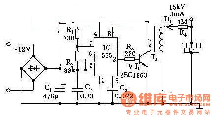
This high voltage generator is capable of producing a stable high voltage exceeding 8kV. The circuit design is straightforward, ensuring stability and reliability. It consists of a step-down rectifier, a voltage regulator circuit, an 18kHz multivibrator-type oscillator, and a...
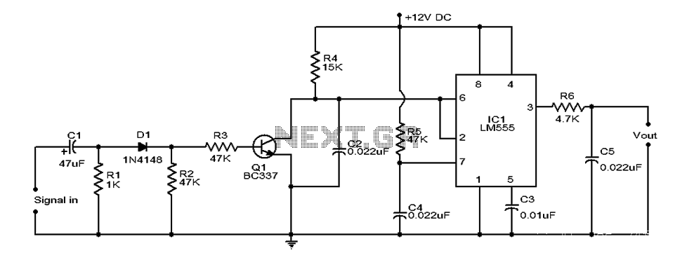
This document provides an overview of a simple circuit diagram for frequency (F and V) voltage conversion. It describes a digital frequency meter circuit primarily based on the LM555 timer IC, which is commonly used in various applications, including...
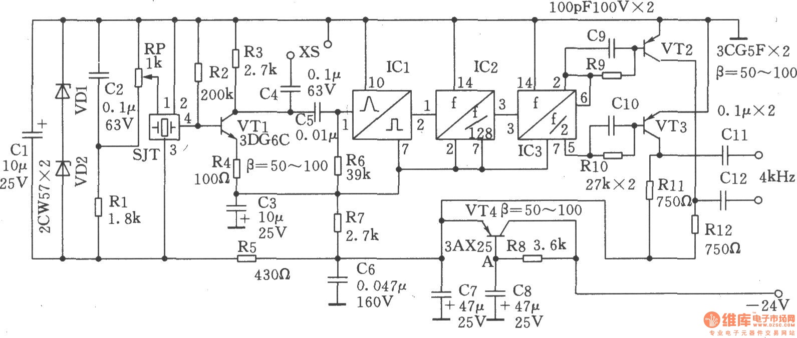
The circuit SJT is a 1024 kHz warming crystal oscillator. The circuit is illustrated in the accompanying chart. Due to the low output signal level, a transistor (VT1) is employed as a buffer amplifier. The base bias resistor (R2)...
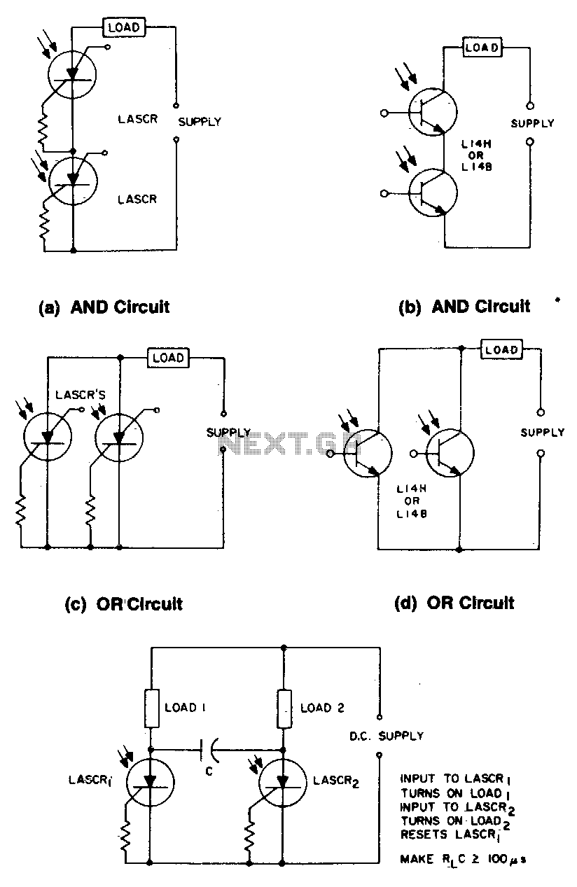
These circuits illustrate some of the common logic functions that can be implemented. The provided circuits serve as examples of fundamental logic functions utilized in digital electronics. Logic functions are the building blocks of digital systems, enabling the execution of...
The Astable Multivibrator, which is generally used as a signal generator, is once again used here to generate the desired frequencies. It is an excellent example of the fact, how versatile simple basic electronic circuit can be. It seems...