
Low-voltage oscillator features increased spectral purity

The described circuit modification enhances the performance of crystal oscillators by addressing the critical issue of mode excitation in quartz crystals. The configuration of grounding the transistor's emitter through an inductor not only aids in overcoming low current levels but also optimizes the startup conditions for vibration. The inductor L1 plays a pivotal role in increasing the voltage gradient across the crystal plates, which is essential during the transient phase immediately following power application. By ensuring that the crystal can achieve the necessary energy levels for startup, the circuit effectively mitigates the risks associated with unwanted mode excitation.
In the context of overtone crystals, the analysis reveals a beneficial relationship between impedance characteristics and frequency. The shift from inductive to capacitive impedance as the frequency transitions from the fundamental to the overtone allows for a more stable and reliable oscillation at the desired frequency. Additionally, the low-pass behavior of the transfer function serves to filter out higher harmonics, resulting in a cleaner output signal.
The practical implications of this modification are significant, particularly in industrial communication applications where reliability and signal integrity are paramount. The marked reduction in failure rates from 23% to near-zero with the modification underscores its effectiveness. Moreover, the substantial decrease in total harmonic distortion from 28% to 0.32% illustrates a remarkable improvement in signal quality, making this circuit modification a valuable enhancement for crystal oscillator designs intended for low-voltage and high-performance applications.A common problem in crystal sinusoidal oscillators is the excitation of unwanted modes of the quartz crystal that degrade the spectral purity of the oscillator. This problem is significant in overtone crystals, particularly if the oscillator is intended for low-voltage applications.
In this case, there`s a compromise between the operating point of the transistor and the drive level of the crystal. If the operating point of the transistor produces a low current level in the crystal, it can`t reach the minimum energy for correct vibration startup. The proposed circuit is a simple modification of a Colpitts oscillator, in which the transistor`s emitter is grounded through an inductor ( see the figure ).
The inductor L1 increases the voltage gradient in crystal plates during the transient response of the oscillator (after power is applied), facilitating the crystal vibration startup. A detailed analysis reveals that, in overtone crystals, the impedance is inductive at the crystal fundamental frequency, whereas this impedance becomes capacitative at the desired overtone.
Therefore, the desired overtone oscillation will be easily started and the undesired fundamental frequency perturbations are avoided. In addition, the overall transfer function has a low-pass behavior that eliminates higher harmonics in the oscillator output.
This circuit has been used in the production of a 27-MHz oscillator for an industrial communication application. Without the proposed modification, 23% of the oscillators failed, with the failure rate noticeably dependent on the production series (manufacturer reference) of the crystal.
With the modification shown, practically all of the oscillators run correctly. On the other hand, the total harmonic distortion (THD) of the oscillator shown, when L1 is replaced by a 4. 7k resistor (classical Colpitts oscillator), is 28%. With the proposed modification (inductor L1), the distortion is reduced to 0. 32%. In all of these measurements, the power supply was 3. 3 V. 🔗 External reference
Related Circuits
Figure 1 illustrates the VFO oscillator circuit operating within the frequency range of 10.58 to 10.74 MHz. This circuit is a redesigned version of a previously presented Colpitts oscillator, with a clearer representation. The inductor, labeled "L," has an...
The world is full of xtal oscillators twiddled by digital designers lacking in the analog design knowledge necessary. Just look at all the PC real time clocks that lags or leads by several minutes per day. And they eat...
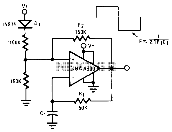
This self-starting fixed-frequency oscillator circuit provides excellent frequency stability. R1 and C1 form the frequency-determining network, while R2 delivers the regenerative feedback. Diode D1 improves stability by compensating for the difference between VaH and VsurrLY. In applications where a...
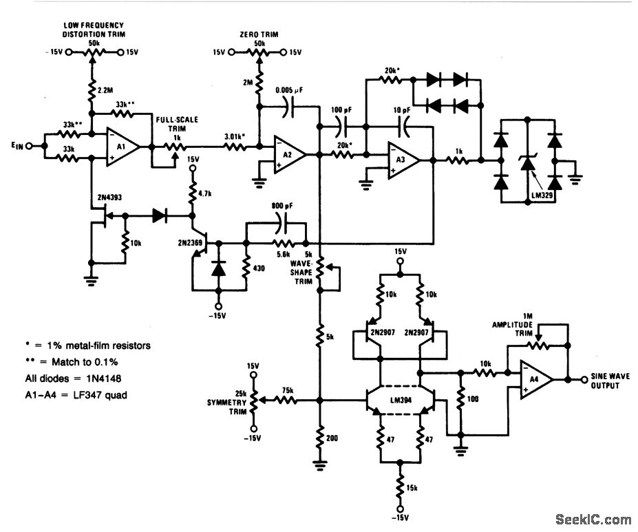
For a 0- to 10-V input, this circuit generates sine-wave outputs ranging from 1 Hz to 20 kHz, achieving linearity better than 0.2%. The distortion level is approximately 0.4%, and both the frequency and amplitude of the sine-wave output...
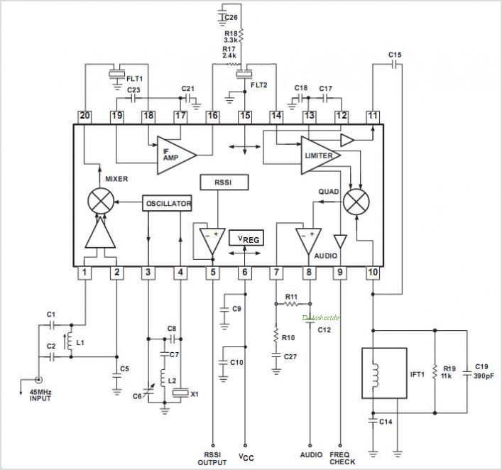
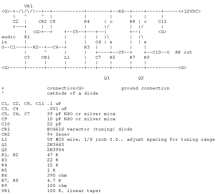
The SA608 is a low-voltage, high-performance monolithic FM intermediate frequency (IF) system that includes a mixer, oscillator, two limiting intermediate frequency amplifiers, a quadrature detector, a logarithmic received signal strength indicator (RSSI), a voltage regulator, and audio and RSSI...
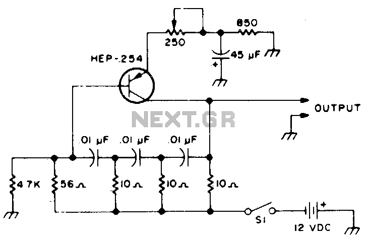
The following transistors may be used: HEP-254, OC-2, SK-3004, AT30H. To increase the frequency, decrease the value of the capacitors in the ladder network. The transistors listed, HEP-254, OC-2, SK-3004, and AT30H, can serve various roles in electronic circuits, particularly...