
10.58 to 10.74 mhz vfo oscillator circuit
The VFO oscillator circuit is a critical component in various applications, including communication systems and signal processing. The Colpitts oscillator configuration is particularly favored for its stability and ease of tuning. The choice of components, such as the T50-6 core inductor and the specific capacitor types, is essential for achieving the desired performance characteristics. The inductance and capacitance must be carefully selected to ensure that the resonant frequency falls within the specified range of 10.58 to 10.74 MHz.
In practical implementations, the layout of the circuit can significantly impact performance, particularly in high-frequency applications. Stray inductance and capacitance can alter the expected resonant frequency, necessitating careful circuit board design and component placement to minimize these effects. Additionally, the use of high-quality capacitors, such as Silvered Mica or COG types, is crucial for maintaining low losses and stable frequency performance.
The operational principles of resonant circuits should also be understood in the context of their application. For instance, in a parallel resonant circuit, the impedance at the resonant frequency is at a maximum, resulting in minimal current flow through the circuit at that frequency. In contrast, a series resonant circuit presents a minimum impedance at resonance, allowing maximum current flow. This behavior is exploited in various applications, including RF amplifiers and filters, where selective frequency response is required.
Designers must also consider the impact of temperature variations and component tolerances on the oscillator's frequency stability. Implementing temperature compensation techniques and utilizing components with tight tolerances can enhance the reliability of the VFO circuit in varying environmental conditions. Overall, a comprehensive understanding of the theoretical and practical aspects of resonant circuits is essential for engineers working on high-frequency oscillator designs.Figure 1 shows the 10. 58 to 10. 74 MHz VFO oscillator circuit. Yes, this is the same circuit that was presented last, but I`ve re-designed to show the Colpitts oscillator more clearly. "L" is approximately 1. 5 uh, 19 becomes a core T50-6 (yellow). The value of C6 is found experimentally. I 69 pF (47 pF to 22 pF and a parallel). More information abo ut this during check-out. "L" and the VVC with C6 form the parallel-tuned circuit that determines the frequency of the VFO. The CVV is a MV2104. Capacitors marked with an asterisk are required Silvered Mica, COG or NPO. You might wonder how the component values for the resonance circuit is determined. Well, when Jupiter aligns with Mars and Mercury on the cusp of the new moon, if the inductive reactance equals the capacitive reactance, then we have a resonance circuit. For a given frequency there are infinite combinations of L and C is a resonance circuit. Experience shows that the variable capacitors and VVC in the range of 5 to 300 pF pF are quite practical.
Combine this with the fact that UH 1. 5 coil and a capacitor of 150 pF resonate near the frequency of interest, and has the component values for the resonance circuit this VFO. You can find the formulas to calculate all this in your manual if you like to do arithmetic. The values of the components actually used in the circuit to take into account "stray" inductance and capacitance that occurs in the real world.
More information about this during check-out. Resonant circuits are fascinating creatures! Although I did not go into a theoretical discussion, there are some fundamental characteristics of resonant circuits that you (and me) should be considered in the construction of VFO, filters, amplifiers, etc. There are two types of resonant circuits commonly used are the series resonant circuit and parallel resonant circuits, as shown below.
Here are two important things to consider: Parallel resonant circuits reduce the flow of AC current in the resonant frequency (and pass all other frequencies) pass resonant series circuit of alternating current in the resonant frequency (and mitigate all the other frequencies). 🔗 External reference
Related Circuits
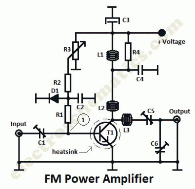
This is a 1 watt FM amplifier with a robust design that can be used to amplify an RF signal in the 88 to 108 MHz band. It is highly sensitive when utilizing quality RF power amplifier transistors, trimmers,...
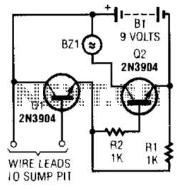
A common collector amplifier drives a 2N3904 switch to sound alarm BZ1. The wire leads to a water sensor or sump pit, level switch, etc. It is used to allow the alarm to operate and be mounted in a...
This circuit is similar to the LED clock using 12 neon indicator lamps instead of LEDs. It operates from 2 high capacity ni-cad cells (2.5 volts) which keep it going for a couple weeks. High voltage (70 volts) for...
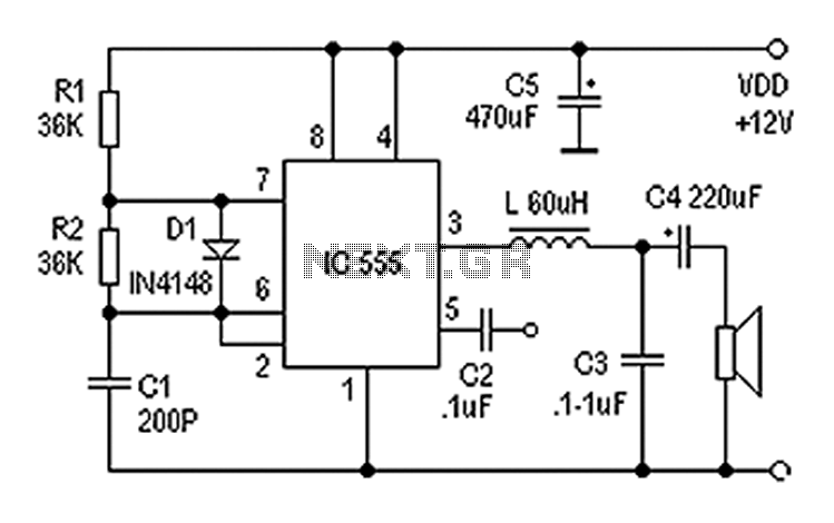
Also known as a digital amplifier, the Class-D amplifier is characterized by its compact size and high efficiency. This circuit utilizes a 555 timer IC to create a Class D amplifier. The 555 timer operates as a controllable multivibrator,...
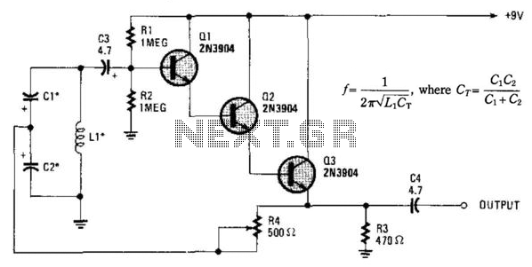
Essentially, this is a Hartley oscillator utilizing a triple-emitter follower, suitable for audio and low radio frequencies. The frequency is determined by the components, and at 1 kHz, a typical capacitor value would be 4.7 µF tantalum, although this...
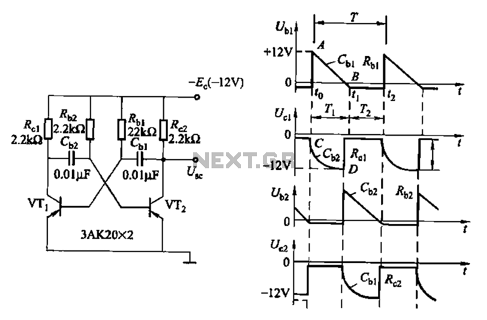
Also known as a no-shot multivibrator, this circuit is often utilized as a pulse (square wave) signal source. The astable flip-flop functions as a strong positive feedback amplifier, with its two branches coupled by an RC timing circuit, resulting...
Warning: include(partials/cookie-banner.php): Failed to open stream: Permission denied in /var/www/html/nextgr/view-circuit.php on line 713
Warning: include(): Failed opening 'partials/cookie-banner.php' for inclusion (include_path='.:/usr/share/php') in /var/www/html/nextgr/view-circuit.php on line 713