
lowvoltage ac voltmeter
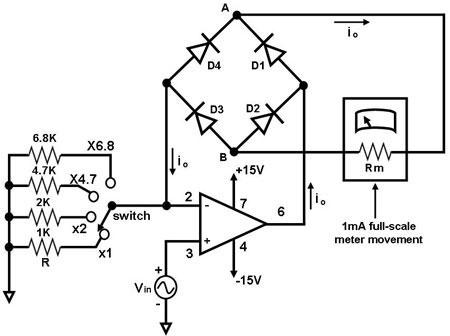
The circuit employs an operational amplifier (op-amp) in a non-inverting configuration, which amplifies the input signal. The diode bridge rectifier is composed of four diodes arranged in a bridge configuration, allowing for full-wave rectification of the AC signal. This configuration ensures that both halves of the AC waveform contribute to the output, thus providing a more stable and continuous DC signal to the ammeter.
The operational amplifier is powered by a dual power supply, typically providing positive and negative voltage rails, which are necessary for accurate amplification of both positive and negative input signals. The feedback loop of the op-amp includes the diode bridge, which serves to convert the amplified AC signal into a pulsating DC signal.
The ammeter is calibrated to measure the average current, which corresponds to the rectified output of the op-amp. The relationship between the input voltage (Vin) and the output current (io) is crucial for understanding the operation of the circuit. The calibration process involves adjusting the circuit to ensure that the ammeter reads the root mean square (RMS) value of the input voltage accurately, which is essential for applications requiring precise voltage measurements.
In summary, this circuit effectively demonstrates the use of an operational amplifier in conjunction with a diode bridge rectifier to measure AC voltage through a DC ammeter, with a careful emphasis on calibration for accurate readings. The design principles and components involved are fundamental in various electronic applications, particularly in measurement and signal processing systems.The main component of this circuit is an operational amplifier (such as the 741 or 351), configured as an amplifier whose feedback circuit is a diode bridge full-wave rectifier. An ammeter is attached to the rectifier circuit as shown in Figure 1 so that the op amp`s output current in both the positive and negative cycles flows through it in only
one direction. In effect, the average of the op amp`s output ac current io, which passes through the ammeter as a dc current, is measured by the ammeter. With full wave rectification, the meter current is given by: io = 0. 9 Vin/R, or Vin = 1. 1 ioR. Note that this project requires calibration so that the meter will register the rms value of the input voltage Vin.
🔗 External reference
Related Circuits
The circuit is a comparator that measures the voltage of a car battery in steps of 1 Volt. The voltage measurement is performed by comparing the battery voltage, applied to the inverting inputs of amplifiers, against reference voltages produced...
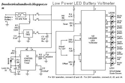
This is a low power voltmeter circuit designed for use with alternative energy systems that operate on 12V and 24V batteries. The voltmeter features an expanded scale that indicates small voltage steps within the 10 to 16 volt range...
When using an analog meter to set the output of a power supply for testing 12-volt equipment, an expanded voltmeter scale offers significant advantages in accuracy compared to a linear scale. Figure 1 illustrates the original meter scale alongside...
The input stage of this voltmeter circuit utilizes an operational amplifier and diode feedback to create a linear peak value rectifier circuit. A partial pressure isolation through resistors R1 and R2 directs the signal to a dual multi-channel BCD...
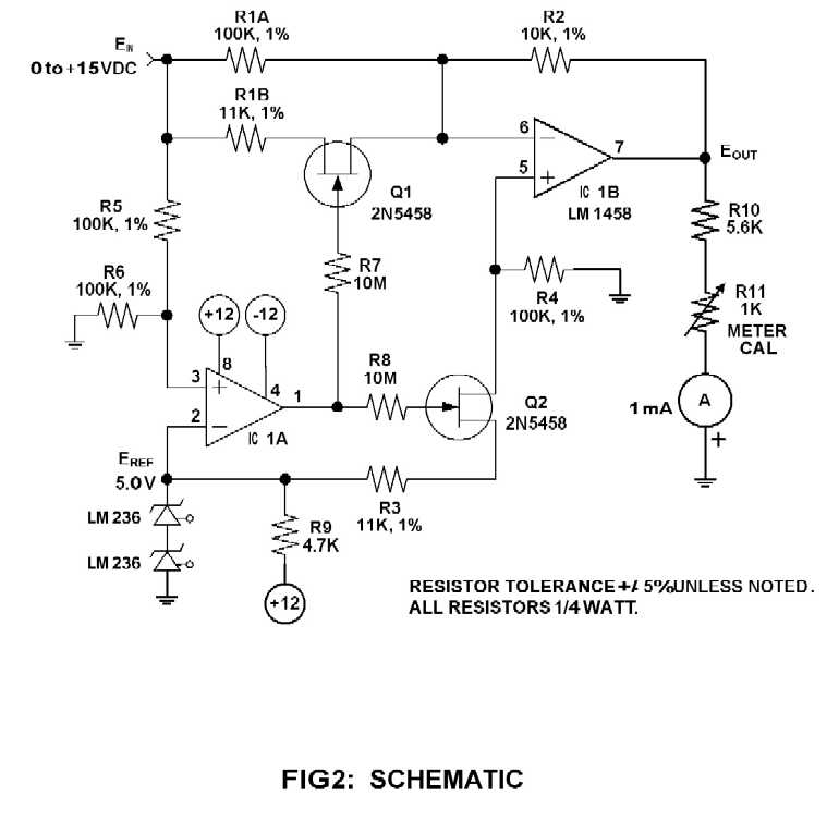
This circuit is a series-FET Voltmeter known as FETVM. The FETVM is designed to replace the function of a vacuum tube voltmeter (VTVM) while simultaneously providing a means to clean the appliance cord. Additionally, the drift rate of this...
This is an easy to build, but nevertheless very accurate and useful digital voltmeter. It has been designed as a panel meter and can be used in DC power supplies or anywhere else it is necessary to have an...
Warning: include(partials/cookie-banner.php): Failed to open stream: Permission denied in /var/www/html/nextgr/view-circuit.php on line 713
Warning: include(): Failed opening 'partials/cookie-banner.php' for inclusion (include_path='.:/usr/share/php') in /var/www/html/nextgr/view-circuit.php on line 713