
EXPANDED SCALE DC VOLTMETER
The circuit described utilizes an analog meter for measuring voltage outputs from a power supply configured for 12-volt equipment testing. The expanded voltmeter scale is crucial for enhancing measurement accuracy, particularly in applications where precise voltage readings are necessary. The reference voltage, Eref, is generated using two LM236 diodes, which provide stability and precision in the voltage reference.
The resistors R2 and R4 are maintained at their linear region values to ensure consistency in the circuit's performance. The selection of R1 at 10K is pivotal, as it establishes a direct relationship between input and output voltages in the expanded region, allowing for precise calibration of the analog meter.
Calculating the value of R3 at the inflection point, where Ein is 10 volts and Eout is -1 volt, is essential for optimizing the circuit's performance. The parallel configuration of R1A and R1B ensures that the effective resistance matches the design requirements. The inclusion of JFET resistance in the calculations enhances the overall accuracy of the output readings.
The operational amplifier IC1A serves as a comparator, crucial for determining the switching behavior of the JFETs (Q1 and Q2). This switching action is what enables the transition between the linear and expanded scales on the analog meter. The configuration of the second operational amplifier, IC1B, is dynamically altered based on the comparator's output, allowing for flexibility in measurement modes.
Resistors R5 and R6 form a voltage divider that sets the threshold for the comparator's switching point, allowing for adaptability in the measurement ranges. If a lower starting point for the expanded scale is desired, a single LM236 can be employed to provide a 2.5-volt reference, necessitating recalibration of the resistors for different ranges.
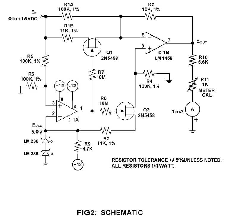
Overall, this circuit design exemplifies a sophisticated approach to voltage measurement, balancing precision with adaptability, making it suitable for a variety of testing scenarios in electronic applications.When using an analog meter to set the output of a power supply used for testing 12-volt equipment, an expanded voltmeter scale has a decided advantage and accuracy over a linear scale. Figure 1 shows the original meter scale and the expanded scale used in this example. Eref is a 5-volt reference voltage set by the two LM236 reference diodes. Keep R2 and R4 the same values as in the linear region. Setting R1 = 10K gives a 1 volt output for a 1 volt input relationship in the expanded region. Calculate for R3 when at the inflection point when Ein = 10 and Eout = -1. Note that R1 here is the parallel combination of R1A and R1B. For higher accuracy the resistance of the JFETs of about 150 ohms can be included in the calculations of R3 and R1B. One of the LM1458 op amps (IC1A) is used as a comparator to drive the gates of the JFETs (Q1, Q2) which switches the other op amp`s (IC1B) configuration between the inverting and the differential amplifier.
The point where the comparator switches is the inflection point on the operating curve, i. e. where the meter changes from a linear scale to the expanded scale. To set up for different ranges, the R5 and R6 divider determines where the comparator switches. If desired to start the expanded portion below 5 volts, a single LM236 can be used providing a 2. 5 volt reference voltage. For other ranges the resistors will have to be recalculated from the above equations. Note that at the inflection point Ein and Eout must be the same for both equations (I) and (III). 🔗 External reference
Related Circuits
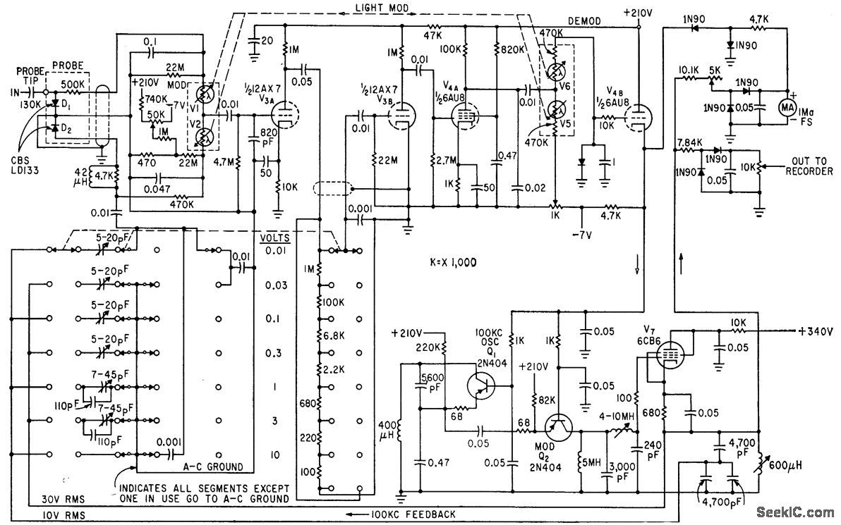
The circuit generates a low-frequency waveform with an amplitude that corresponds to an unknown RF voltage, utilizing a photochopper modulator (VI-V2) as an error detector. This arrangement provides seven voltage ranges from 10 mV RMS to 10 V RMS...
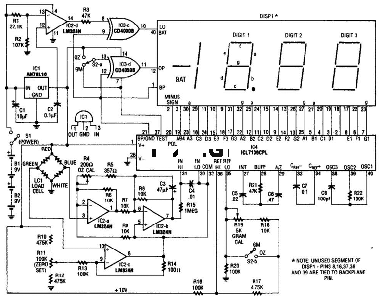
An electronic scale utilizes a pressure transducer (load cell) along with an analog-to-digital (A/D) converter to operate a digital display. The scale's range is determined by the specifications of the load cell, and the display is calibrated in suitable...
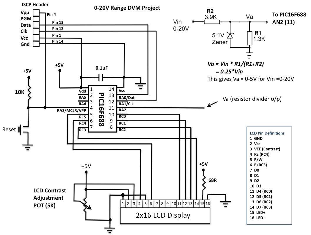
This is another version of an older digital voltmeter (DVM) project that was based on the PIC12F683 microcontroller. The previous version displayed the measured voltage on an LCD driven serially by the PIC12F683 using three I/O pins. The new...
This circuit is designed to provide an inexpensive way to create a High Impedance Voltmeter while making use of an inexpensive analog or digital multimeter. When measuring voltages in high resistance circuits, the resistance of the voltmeter itself has...
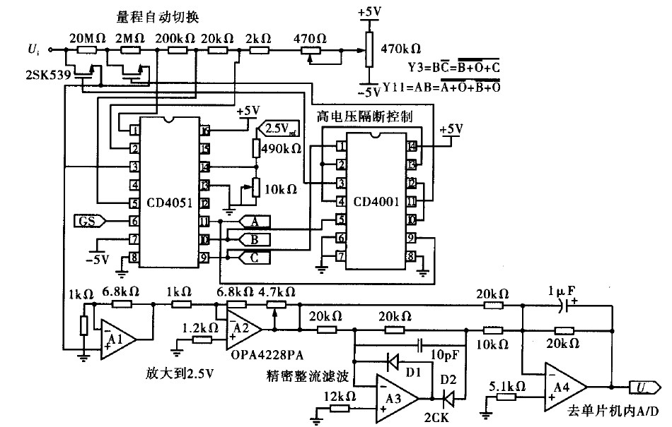
Voltage measurement is a fundamental aspect of electronic technology today, with increasing demands for accuracy and functionality in instruments. This is particularly critical when measuring signals with significant phase differences, as it is essential to ensure the accuracy of...
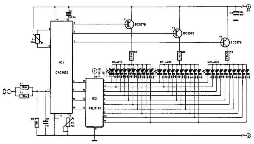
The voltage to be measured is digitized in an analog-to-digital (A/D) converter and then displayed in three decimal digits. The display consists of three groups of 10 LEDs. The meter can only be used for measuring direct voltages. The...