
Luxury Car Interior Light

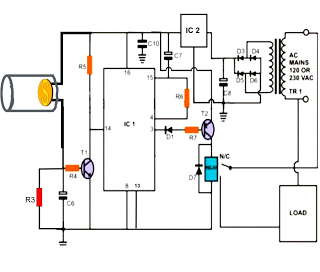
This circuit utilizes a simple yet effective design to provide a gradual dimming feature for interior lights in vehicles. The core components include a relaxation oscillator and a comparator, which work together to create a smooth transition in light intensity. The circuit operates efficiently with minimal power consumption, making it suitable for automotive applications where battery life is a concern. The adjustable components allow customization of the dimming effect, accommodating various user preferences. The circuit's robustness against voltage spikes ensures longevity and reliability in automotive environments, where electrical noise can be prevalent. The compact design facilitates easy integration into the vehicle's interior, ensuring that the functionality does not compromise aesthetics. Overall, this circuit represents a practical solution for enhancing the interior lighting experience in mid-range and older vehicles, aligning with modern standards of convenience and comfort.This circuit is much more modest, but certainly still worth the effort. It provides a high quality interior light delay. This is a feature that is included as standard with most modern cars, although the version with an automatic dimmer is generally only found in the more expensive models. With this circuit it is possible to upgrade second hand an d mid-range models with an interior light delay that slowly dims after the door has been closed. The dimming of the light is implemented by means of pulse-width modulation. This requires a triangle wave oscillator and a comparator. Two opamps are generally required to generate a good triangle wave, but because the waveform doesn`t have to be accurate, we can make do with a single opamp. This results in the circuit around IC1. A, a relaxation oscillator supplying a square wave output. The voltage at the inverting input has more of a triangular shape. This signal can be used as long as we do not put too much of a load on it. The high impedance input of IC1. B certainly won`t cause problems in this respect. This opamp is used as a comparator and compares the voltage of the triangular wave with that across the door switch.
When the door is open, the switch closes and creates a short to the chassis of the car. The output of the opamp will then be high, causing T1 to conduct and the interior light will turn on. When the door is closed the light will continue to burn at full strength until the voltage across C2 reaches the lower side of the triangle wave (about 5 V).
The comparator will now switch its output at the same rate of the triangle wave (about 500 Hz), with a slowly reducing pulse width, which results in a slowly reducing brightness of the interior light. R8 and C3 protect the circuit from voltage spikes that may be induced by the fast switching of the light.
The delay and dimming time can be adjusted with R6 and C2. Smaller values result in shorter times. You can vary the dimming time on its own by adjusting R1, as this changes the amplitude of the triangle wave across C1. R7 limits the discharge current of C2; if this were too big, it would considerably reduce the lifespan of the capacitor.
There is no need to worry about reducing the life of the car battery. The circuit consumes just 350 µA when the lamp is off and a TLC272 is used for the dual opamp. A TL082 will take about 1 mA. These values won`t discharge a normal car battery very quickly; the self-discharge is probably many times higher. It is also possible to use an LM358, TL072 or TL062 for IC1. R8 then needs to have a value between 47 and 100 . Since T1 is always either fully on or fully off, hardly any heat is generated. At a current of 2 A the voltage drop across the transistor is about 100 mV, giving rise to a dissipation of 200 mW.
This is such a small amount that no heatsink is required. The whole circuit can therefore remain very compact and should be easily fitted in the car, behind the fabric of the roof for example. 🔗 External reference
Related Circuits
The minimum voltage required for this circuit is 8 volts, while the maximum voltage is 28 volts. It can be used to amplify audio signals in electronic devices such as radios, DVDs, MP4 players, and MP5 players. The circuit...
This circuit illustrates a car audio amplifier utilizing the TDA7381 integrated circuit (IC). The TDA7381 audio amplifier IC allows for the design of a straightforward 4x25 watts car radio. The TDA7381 is a high-performance audio amplifier designed specifically for automotive...
The circuit diagram depicts a simple and effective subwoofer filter designed to operate from a 12V DC supply. This circuit is particularly useful in car subwoofer applications. It functions as a low-pass filter with an adjustable pass frequency ranging...

Color TV subcarrier generator. The crystal shown is for 3.58 MHz. The ECG1131 noted on the schematic is a chroma signal amplifier. The ECG1132 is a 16-pin DIP (courtesy of GTE Sylvania Incorporated). The color TV subcarrier generator is an...
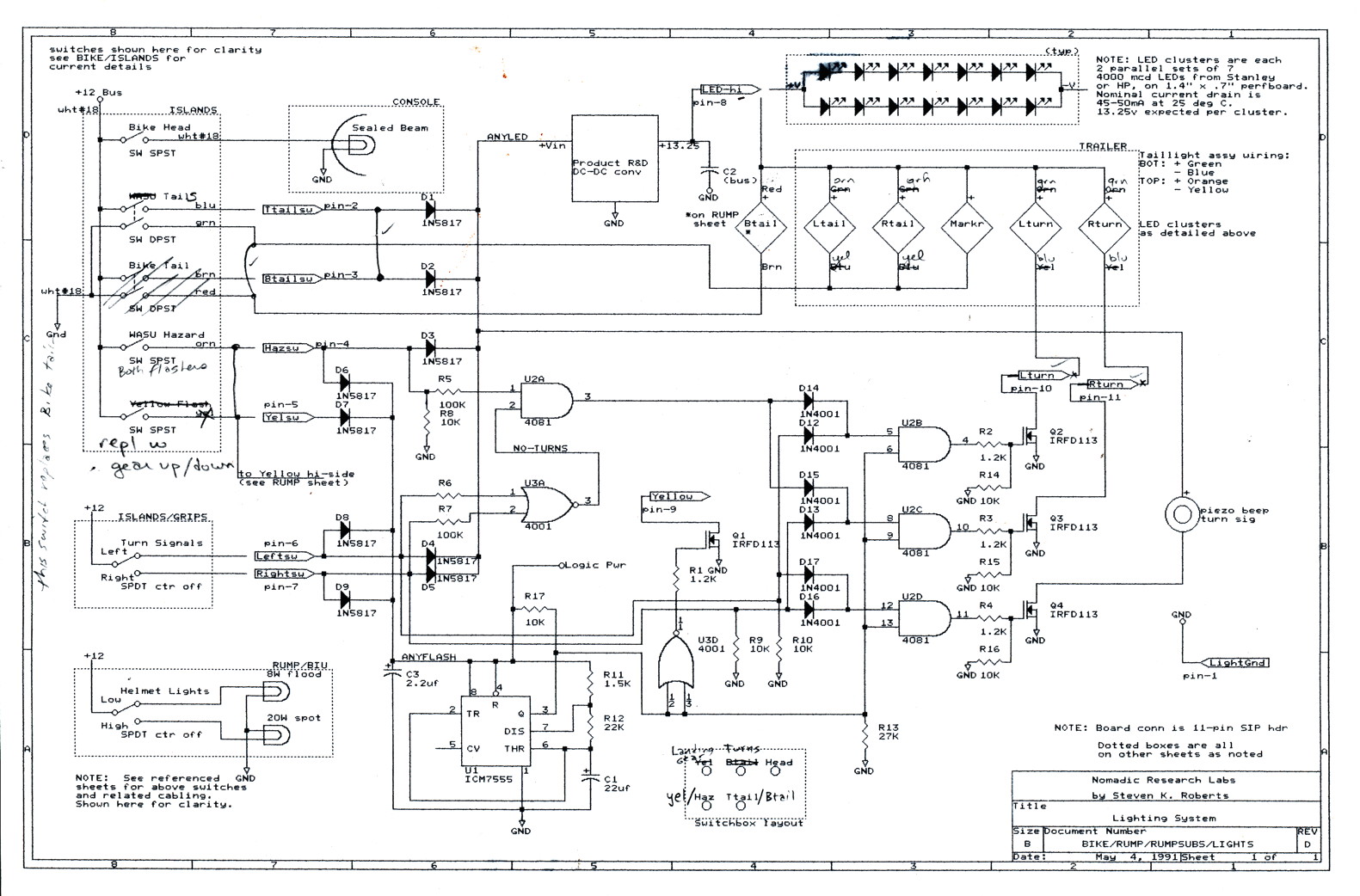
This second issue of the Bikelab Notes, published during the development of BEHEMOTH at Sun Microsystems, focuses on high-brightness LED taillight assemblies that were not commercially available at the time, making this a unique project. The author also comments...
The following post illustrates a simple light-operated remote control circuit that can be activated by an ordinary flashlight or, more effectively, through a laser beam unit (keychain type). The Light Dependent Resistor (LDR) is connected between the base of...