
car subwoofer filter using op
The circuit utilizes the TL072 operational amplifier, which is known for its low noise and high slew rate, making it suitable for audio applications. The configuration of IC1A as a buffer serves to isolate the audio source from the load, ensuring that the signal integrity is maintained while preventing loading effects that could distort the audio signal.
The DPDT switch S1 allows the user to select between different configurations, thus enabling the subwoofer to be in phase with the other speakers in the system. This feature is crucial for achieving optimal sound quality and coherence in multi-speaker setups, particularly in automotive environments where space and acoustics can be challenging.
The low-pass filter formed by IC1B is essential for allowing only the desired bass frequencies to pass through to the subwoofer, effectively blocking higher frequencies that could lead to distortion. The adjustable pass frequency, controlled by the dual gang potentiometer R13, provides flexibility in tuning the filter to suit different musical genres or personal preferences, enhancing the listening experience.
The use of potentiometer R7 for level control allows the user to adjust the output level of the subwoofer, ensuring that it blends well with the rest of the audio system. This feature is particularly important in car audio systems, where cabin acoustics can vary significantly, and the balance between bass and other frequencies must be carefully managed.
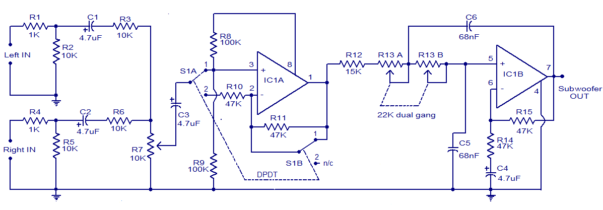
Overall, this subwoofer filter circuit is a practical solution for enhancing the low-frequency performance of car audio systems, providing users with the ability to customize their sound experience effectively.Here is the circuit diagram of simple and easy subwoofer filter which will be operated from a 12V DC supply. Such a circuit is incredibly helpful in Car subwoofer applications. The circuit is nothing however a low pass filter whose pass frequency will be adjusted between 60 to 160 Hz.
The circuit is intended round the TL072 twin BIFET opamp IC. Ou t of the 2 opamps within the chip, IC1A is wired as a buffer. The left and right audio inputs when mixing is fed to the input of the IC1A using the DPDT switch S1. Switch S1 is that the section control switch which might be used to create the subwoofer in section with different speakers.
When S1 is in position {2, 180 degree phase shift are induced. POT R7 will be used for controlling the level. IC1B forms the low pass filter whose pass frequency will be controlled by adjusting the twin gang POT R13. 🔗 External reference
Related Circuits
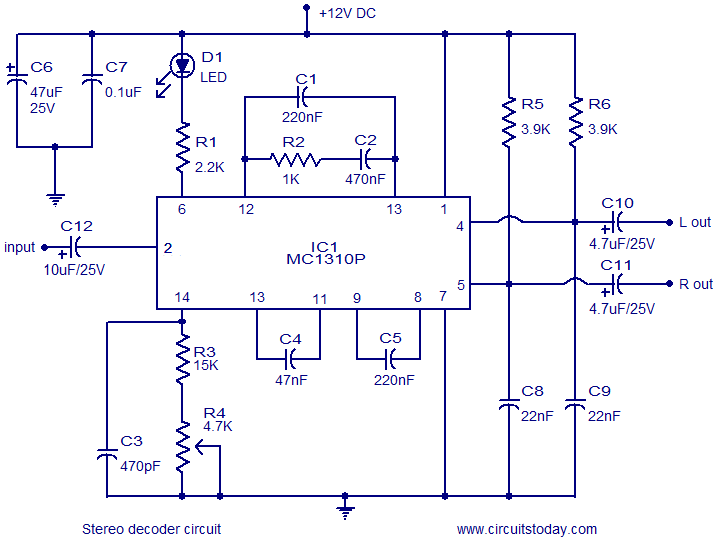
A simple FM stereo decoder circuit utilizing the MC1310P integrated circuit (IC). It operates at 12V and provides a channel separation of 40dB, making it suitable for stereo FM receivers. The FM stereo decoder circuit based on the MC1310P IC...
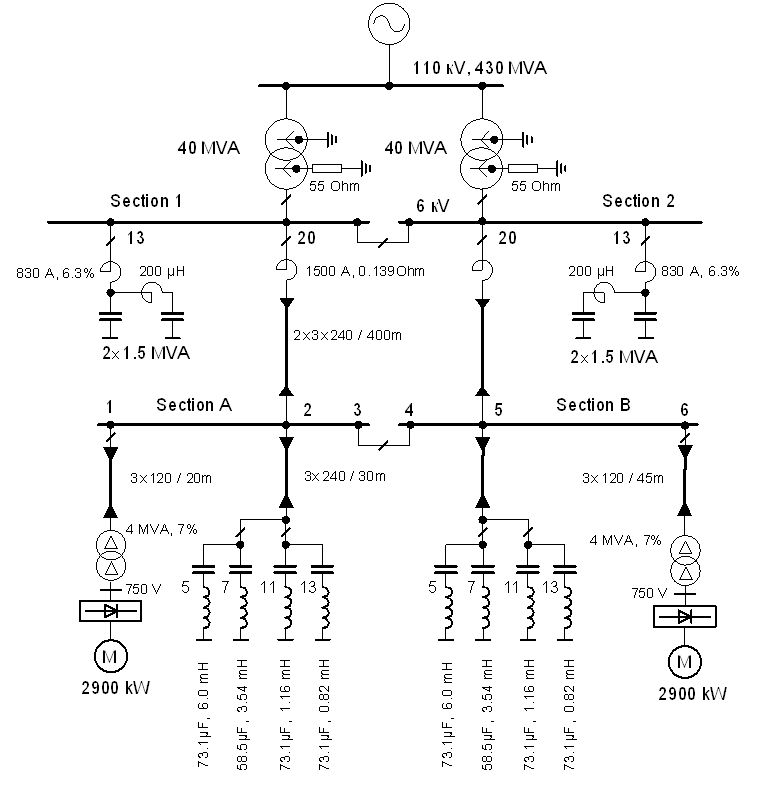
The vertical line indicates the instance of the 5th harmonic filter connection. The diagram illustrates the power system with the designed group of single-tuned filters for a system with a DC drive supplied by a 6-pulse controlled rectifier: PN...
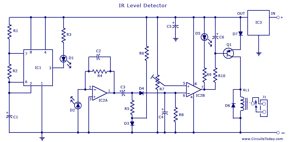
An infrared (IR) sensor or detector circuit diagram utilizing a 555 integrated circuit (IC), primarily employed as a water level or liquid level sensor and proximity detector circuit. The described circuit employs a 555 timer IC configured in a monostable...
Inspired by a previous project, a unique design was developed that incorporates an umbrella capable of playing musical notes when pressed. For additional information regarding the 4051 chip, which functions as a multiplexer or demultiplexer, refer to resources available...
VA-RICH Power consumption: -2V current draws 34 mA, +2V current draws 5 mA. Total power consumption is 68 mW. Spark protection: Spark protection works, but the spark current burns the trace from pad to input transistor, which makes the...
Heavy-duty portable charger for USB devices (phones, iPad, etc.). Have you ever needed to charge your phone on the go? Unable to find a wall socket to charge your iPod?.. The heavy-duty portable charger is designed to provide a reliable...