
LWDAQ Driver (A2037) Manual
The LWDAQ Driver (A2037) serves as a pivotal component in data acquisition systems, particularly in high-energy physics experiments such as those conducted at CERN's ATLAS detector. The driver is equipped with eight LWDAQ sockets, facilitating connections to various devices and multiplexers, which are integral for managing extensive data collection processes from numerous sensors. Each socket is capable of delivering power at multiple voltage levels (±15V and +5V), ensuring compatibility with a wide range of LWDAQ devices.
The A2037's architecture allows for efficient power management, with the ability to monitor voltage levels and total current consumption, thereby providing essential feedback for system integrity. The design includes a reset functionality that not only resets the driver but also the connected devices, ensuring that the system can recover from potential errors or malfunctions quickly.
Signal processing capabilities are a highlight of the A2037, which can handle low-voltage differential signals through different filtering and digitization techniques. This flexibility enables it to cater to varying requirements for data acquisition, from low-frequency measurements to high-speed data capture. The incorporation of both 16-bit and 8-bit ADCs allows for a choice between high-resolution or faster sampling rates, depending on the specific application needs.
The onboard static RAM provides a substantial memory buffer for storing measurement data, which is critical in experiments where data integrity and retrieval speed are paramount. The programmable logic chip (U1) adds a layer of customization, allowing for tailored functionality to meet specific experimental protocols.
Connectivity options are robust, with provisions for both USB and Ethernet adaptors, facilitating integration into broader data acquisition networks. The design also considers physical installation aspects, with mounting options for additional hardware and a user-friendly interface for operational status monitoring.
In summary, the A2037 LWDAQ Driver is engineered to support complex data acquisition tasks in demanding environments, combining power management, signal processing, and connectivity features to deliver a comprehensive solution for experimental setups in particle physics and other scientific fields.The LWDAQ Driver (A2037) is a Long-Wire Data Acquisition ( LWDAQ ) Driver. You will find an introduction to the LWDAQ in the LWDAQ User Manual. The A2037 provides eight LWDAQ driver sockets, each of which may be connected to a LWDAQ device or a LWDAQ multiplexer. We assume you are familiar with the LWDAQ Specification. Those of you converting fr om the Device Driver (A2031) to the A2037 can jump to A2031 Compatibility. Figure: LWDAQ Driver with VME Interface (A2037A). Marked are: (1) the base address switch, (2) reset switch, (3) reset lamp, (4) busy lamp, (5) +15V okay lamp, (6) +5V okay lamp, (7) ’15V okay lamp, (8) test point LEDs, (9) driver sockets, (10) VME J2 connector, (11) VME J1 connector, (12) programming connector, (13) programming power connector, (14) USB adaptor socket, (15) Ethernet adaptor socket, (16) hardware mode jumper field. The A2037 provides eight LWDAQ driver sockets. Each socket provides ±15V and +5V power for LWDAQ devices or multiplexers. The A2037 can provide up to 500 mA at ±15V, and 1000 mA at +5V to all its driver sockets combined. It allows you to monitor the power supply voltages, and to measure the total current drawn from them.
You can cut off power to the driver sockets by writing to a register on the A2037. Turning the LWDAQ power off for a second, and then on again, resets all devices and multiplexers, and restores them to the sleep state. See the Power Supplies section below for more details. The analog signal returned from a device to the driver is a low-voltage differential signal with dynamic range ±0.
5V. The A2037 can handle this signal in three ways. The first is to pass it through a 10-kHz low-pass filter and digitize it with a 16-bit analog-to-digital converter (ADC). The A2037`s adc16 job performs this digitization, stores the result in the driver`s random-access memory (RAM), and increments the driver`s data address (see Data Address section below) by two (see the Sixteen-Bit ADC section below).
The second way to handle the analog signal is to pass it through a 5-MHz low-pass filter and digitize it with an eight-bit ADC. The A2037`s adc8 job digitizes the 5-MHz signal, stores it in RAM, and increments the data address. The third way to handle the analog signal is to clamp it when it sits at a zero-level, and then digitize it with the eight-bit ADC when the signal attains its measurement value (see the Eight-Bit ADC section below).
The A2037`s read job, when applied to a TC255P device, uses its clamp to perform correlated double-sampling of the returned image pixels. To store measurements, the A2037 provides 512 Kbytes of static RAM. You lose the RAM contents if you turn the A2037 power off, but not if you reset the board or turn off power to the driver sockets.
The U1 chip on the A2037 is its programmable logic chip. We describe how to re-program this chip below. Also on the A2037 are sockets for an Ethernet adaptor and a universal serial bus (USB) adaptor (see the Modules section below). The A2037A provides mounting holes for unlocking levers and a front panel. At the time of writing, we have locking levers and front panels, but they do not appear to fit in most people`s VME crates.
The push-button switch on the front of the board is the reset switch. Just below it is the reset light, which should go on when you press the switch. You can also reset the board from the VME crate reset line. When you reset the board, you return programmable logic chip to its reset state. But you do not reset the LWDAQ devices to the sleep state. To restore them to the sleep state, you must turn off the LWDAQ power, or go through all the device addresses and transmit a sleep command to each. The front-panel lamps, all of which are light-emitting diodes (LEDs), have the following functions. The top one is red. It is the reset indicator. The one below is green. It turns on when the A2037 is busy performing an LWDAQ job. The three green lamps below that are driven directly from the LWDAQ power supplies. The top one is connected to +15V, the middle one to +5V, and the bottom one to ’15V. If one of these lamps glows dimly, its supply voltage has dropped. If it does not glow, the power is off. Below the green lamps are four yellow lamps and four red ones. These are test-pin lamps, numbered one through eight from the top down (see the Test Pins section below).
We designed the A2037A for the muon end-cap alignment system of the ATLAS detector at CERN. One hundred and twenty A2037As will operate in VME crates in the USA15 room adjacent to the detector hall. In each crate, a VME-TCPIP Interface, such as the A2064 will make all drivers in the crate available over the local ethernet.
Seven hundred cables, each up to one hundred meters long will connect these drivers to multiplexers in the detector hall, and cables up to ten meters long will connect these multiplexers to nearly six thousand devices. Prior to installation in ATLAS, however, we intend to use the A2037E for use in ATLAS production and quality assurance fixtures.
The A2037E provides an Ethernet with TCPIP interface, which is more convenient for small LWDAQ systems. We used sixteen A2037Es around the rim of the end-cap muon system`s Big Wheels so that we could read out the alignment system during assembly on the cavern wall.
See here for a picture of an A2037E on the rim of the big wheel, and here for a movie showing the size of the bigg wheel. A $ before a numerical value indicates hexadecimal notation. A * before a logic signal name indicates negation. An asserted logic signal is one for which the signal in its name is true. Thus WAKE and *SLEEP are the same signal on a LWDAQ device, but WAKE is asserted when SLEEP is unasserted.
A true logic signal is HI, and a false logic signal is LO. A nibble is four bits, a byte is eight bits, a two-byte is sixteen bits, and a four-byte is thirty-two bits. A bit or nibble marked X can take any value without affecting the statement in which it is mentioned.
When we respond to address $1X, we mean we respond to all addresses $10 to $1F. An LWDAQ component is one that conforms to the LWDAQ Specification. The target device of an LWDAQ system is the unique device that will receive the next command word from the LWDAQ driver. Circuits made by Brandeis may have the same name, but all have unique assembly numbers. The TC255P Head (A2007) is distinct from the TC255P Head (A2029). They have different assembly numbers. This manual uses the generic names for all LWDAQ Driver jobs. Instead of clear job we say move job. Instead of transfer job we say alt move job. Instead of expose job we say wake job. Instead of ab expose job we say toggle job. Suppose we want to set up an instrument consisting of an image sensor, a lens, and an illuminated mask.
We pick the Inplane Sensor Head (A2036), and the Inplane Mask Head ( A2052 ) to perform the image capture and mask illumination respectively. Both the A2036 and the A2052 are LWDAQ devices. Each has a single, shielded RJ-45 socket through which it communicates with our A2037. We connect our two devices to our driver with two LWDAQ cables. An LWDAQ cable is simply an eight-way, straight-through, CAT-5 cable. Our driver and our optical instrument are in separate rooms. The driver is plugged into a VME crate, and we can connect this VME crate to the outside world with the help of a TCPIP-VME Interface ( A2064A ).
The A2064A connects the VME crate to the local 10-Base-T Ethernet. The drivers in the VME crate appear upon the Internet in the same way as a single A2037E would appear on the Internet. The only difference between the two arrangements is that we must specify the VME base address of the VME-resident driver in our data acquisition software.
Instead of using an A2064A, however, you may wish to use your own VME interface and write your own software to communicate directly with the A2037A through its registers. Regardless of the computer upon which it runs, and regardless of the interface between the computer and the VME crate, will read and write bytes from the A2037 control and status registers, and read blocks of data out of the A2037 memory.
This manual is supposed to provide you with enough information to write your own software to interact with the driver. We cause the A2037 to perform data acquisition functions, such as flashing a laser or clearing a CCD image area, by writing byte values to its control registers, and we monitor the progress of these functions by reading byte values out of its status registers.
When we want to retrieve data from the A2037 memory, we can read it out one byte at a time, or two bytes at a time (but not four bytes at a time). The control registers on the A2037 have names like device job register and device address register. The data acquisition computer will display and analyze images of our mask. We run our LWDAQ cables from the instrument room to the driver room, and find that they need to be thirty meters long.
The LWDAQ can handle solid-core CAT-5 cables up to one hundred meters long with no loss of performance, and braided-core CAT-5 cables up to twenty meters long. Therefore, these cables should be solid-core. They may be shielded or unshielded. Now we must plug each cable into a socket on the driver. There are eight driver sockets to choose from. We plug the A2036 to the top socket, and the A2052 into the bottom socket. The driver sends commands to only one device at a time, and we call this device the current target device.
Each device in an LWDAQ has a device address by which we can select it and make it the target device. The top socket on the A2037 occupies addresses $10 to $1F. The bottom socket occupies $80 to $8F. The A2037 assigns sixteen addresses to each socket so that we can use each socket with a sixteen-way multiplexer.
In this case, we have no multiplexers, so the sixteen addresses are redundant. For the benefit of our data acquisition software, however, we pick device address $10 for the A2036 and $80 for the A2052. To select one or other of the devices, we will write these numbers to the A2037`s device address register.
Before we can acquire any data from our devices, we must make sure that the A2037A`s device power supplies are turned on. For versions 1 through 9 of the A2037A firmware, the A2037A turns on its device power supplies upon a software, hardware, or power-up reset.
Starting with version 10 of the firmware, however, the A2037A turns off its device power supplies upon reset. To turn on the power supplies yourself, you must write an odd number to the enable device power register.
To turn off the device poweer, you write an even number to the same register. We consult the A2036 and A2052 manuals. We see that the A2036 is a TC255P Device (type-2) and the A2052 is an LED Device (type-1). 🔗 External reference
Related Circuits
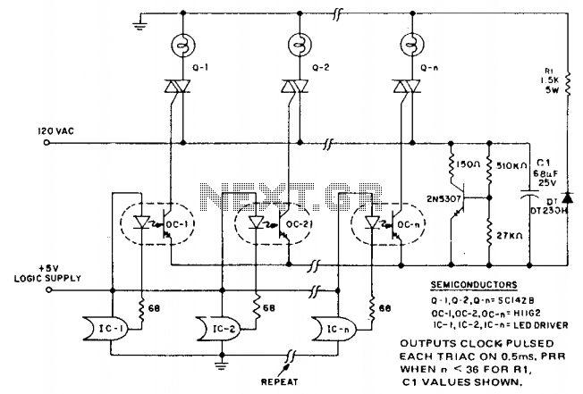
In microprocessor control of multiple loads, minimizing the cost per load is essential. A typical application is a large display that drives arrays of incandescent lamps. This circuit achieves minimal component cost per stage by utilizing optocoupler triggering of...
A 1999 Chevrolet Suburban has non-functional headlights. The fuses and circuit breakers have been checked and found to be operational. According to the owner's manual, the headlamps are protected by a circuit breaker located within the lamp switch, but...
This is a fun and non-dangerous project for those people who like to throw projectiles magnetically. It simply works by placing a ferromagnetic projectile at one end of a coil and pulsing some power in it. The trick is...
Attached are three captures from a L297/L298 board using the same motor at 500, 750, and 900 steps per second on a 36V supply, wired in bipolar parallel (coil resistance = 3.2 ohms). This shows the A-enable signal (blue)...
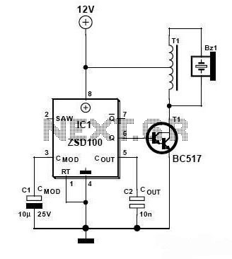
Zetex Semiconductors offers a siren driver integrated circuit (IC) known as the ZSD100, which is designed for use in alarm systems for vehicles and model crafts. By incorporating just a few additional components, as illustrated in the accompanying diagram,...
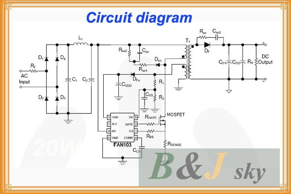
This lighting solution offers over 90% energy savings compared to incandescent or halogen bulbs, with a lifespan exceeding 50,000 hours. It operates without flickering, making it suitable for human eyes, and produces no RF interference or UV radiation. The...