
TB6560 Stepper Motor Driver Boards
The L297/L298 motor driver circuit is a versatile solution for controlling stepper motors, particularly in bipolar configurations. The L298 is a dual H-bridge driver that allows for bidirectional control of the motor, while the L297 provides the necessary control signals, including step and direction inputs. The integration of these components enables precise control over motor steps, facilitating applications such as CNC machines and robotics.
In the described setup, the motor is powered by a 36V supply, which is at the upper limit for many L298 configurations, especially under conditions where back EMF can introduce voltage spikes. The coil resistance of 3.2 ohms suggests that the motor is designed for moderate currents, which are observed in the testing results. The sense voltage measured is indicative of the current flowing through the motor coils, with the relationship defined as 0.5V equating to 1A. This proportionality allows for effective monitoring and control of the motor's operation.
The observed behavior of the current during different stepping rates highlights the importance of inductance in motor performance. At lower stepping rates, the current ramps up more slowly due to the inductive properties of the coils, which is critical for preventing overheating and ensuring the longevity of the motor and driver. As the stepping rate increases, the time available for current build-up decreases, leading to lower RMS current measurements at higher speeds. This behavior emphasizes the necessity of implementing current limiting features in the driver circuit to prevent damage to the motor.
The implementation of a snubber circuit, consisting of a zener diode and a resistor, is a prudent design choice to mitigate voltage spikes caused by back EMF during deceleration. This protection is vital in preserving the integrity of the driver IC and maintaining stable operation. The recommendation to use a lower voltage power supply, ideally capped at 30V for this setup, aligns with best practices for ensuring reliable performance and preventing damage from voltage transients.
In summary, the L297/L298 driver circuit, when correctly configured and protected, offers robust performance for stepper motor applications. Careful attention to voltage levels, current limiting, and protective measures such as snubber circuits are essential for achieving optimal results and ensuring the longevity of the components involved.Attached are 3 captures from my L297/L298 board using the same motor at 500, 750 and 900 steps/sec on a 36v supply, wired bipolar parallel (coil resistance = 3. 2ohm). This shows the A-enable signal (blue) and the sense voltage (red). The sense voltage is directly proportional to the current in the coil (x 2), so. 5v = 1A. At 500stesp/sec the RMS v oltage is 0. 64v, a current of 1. 3A RMS, the peak voltage being 0. 9v equivalent to 1. 8A. You can see that the current doesn`t start to flow (indeed its negative slightly at the start of the cycle which is due to the back emf/collapsing field of the previous cycle) until 0. 7mS into the cycle, it then ramps up due to the inductance of the coils (these being high inductance motors i.
e. not very fast) until it finally gets to the current limit and the driver goes into chopping. At 750stesp/sec the RMS current has dropped to about 1A, the peak still being 1. 8A. This is because the initial start-up and ramp is a greater proportion of the cycle time. At 900steps/sec the current never gets to the set limit before the cycle ends. this is the fastest the motor will go at this voltage and the power output wil be low, the RMS current here is about 0. 5A. I set the board to it`s lowest current setting on the DIP switches to make sure I did not burn out or over heat my stepper motor, I am only testing X-Axis atm.
Powered up the board, and all the lights and the fan came on, Turned it all off and, when I next turned it back on, I was greated with a nice pop / bang, with sparks, and blue / white smoke. I set the board to it`s lowest current setting on the DIP switches to make sure I did not burn out or over heat my stepper motor, I am only testing X-Axis atm.
Powered up the board, and all the lights and the fan came on, Turned it all off and, when I next turned it back on, I was greated with a nice pop / bang, with sparks, and blue / white smoke. Can you turn down the power supply Mine goes down to 32 and up to 40v. it could be that back-emf from the motor had damaged the chip by spiking the supply - I`d limit that board to a 30v supply if it has regulators on-board unless they have an additional dropping zener diode in series.
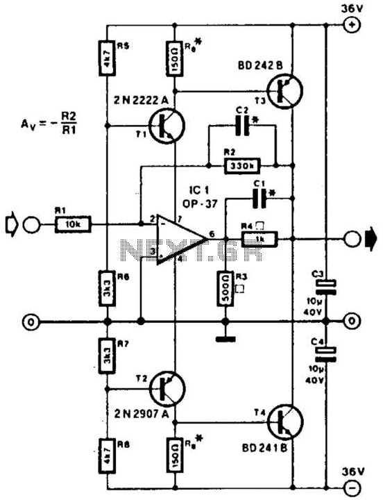
On my board you can see spikes of 65v on deceleration, so I have a snubber (basically a 36v zener and a low ohm resistor) across the supply. Another solution, shown in the attached schematic uses a transistor to the same effect. Thats pretty impressive. any collateral damage as far as you can tell I`d strip the chip off the board and then retest on the 13v supply and confirm other voltages are as expected.
output of regs, logic levels, etc. and compare the voltages on equivalent pins of the remaining drivers - without motors attached. Can you turn down the power supply Mine goes down to 32 and up to 40v. it could be that back-emf from the motor had damaged the chip by spiking the supply - I`d limit that board to a 30v supply if it has regulators on-board unless they have an additional dropping zener diode in series. On my board you can see spikes of 65v on deceleration, so I have a snubber (basically a 36v zener and a low ohm resistor) across the supply.
Another solution, shown in the attached schematic uses a transistor to the same effect. That snubber circuit is very interesting. It`s just what I need. I`m running one of those 50V power supplies that Kip found in "unregulated" mode at 43V. My drivers will smoke at 50V, so I`m nervous. That snubber circuit is very interesting. It`s just what I need. I`m running one of those 50V power supplies that Kip found in "unregulated" mode at 43V. My drivers will smoke at 50V, so I`m nervous. Yes, sadly I wasnt able to find an easy way to turn the volts on those down as they do some strange things with the internal reference line that doesn`t follow the application note for the chip they use. I managed to blow one up quite spectacularly! When I said zener diode I rea 🔗 External reference
Related Circuits
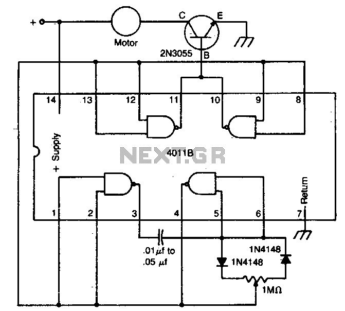
The circuit utilizes a 4011 CMOS NAND gate, a pair of diodes, and an NPN power transistor to create a variable duty-cycle DC source. By adjusting the speed control, the average voltage applied to the motor can be varied,...
This project outlines the construction of a Brushed Motor Electronic Speed Controller (ESC) for cars and boats using a Microchip 12F675 PIC and a limited number of standard components. This ESC is a revised version of an earlier aircraft...
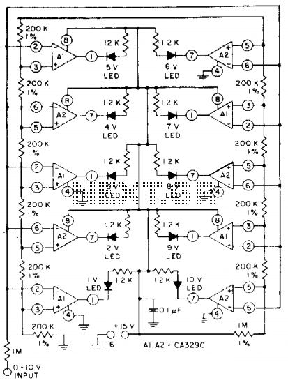
The circuit utilizes CA3290 BiMOS dual voltage comparators. The non-inverting inputs of A1 and A2 are connected to a voltage divider reference. The input signal is applied to the inverting inputs. LEDs are activated when the input voltage reaches...
This line driver is capable of driving low-impedance lines with a maximum output of 70 V peak-to-peak. IC1 functions as a low-noise operational amplifier suitable for operation at 15 V. T1 and T2 serve as voltage regulators for the...
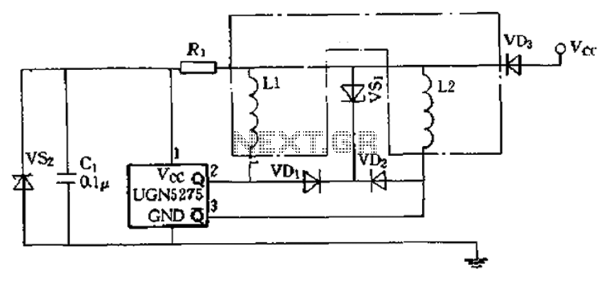
The circuit features almost open collector outputs with a withstand voltage of 60V and a continuous conduction current of 0.3A. The typical voltage drop is 0.4V, with a peak current capability of 9A. It can directly drive two windings...
How to connect and program the Arduino/Atmega168 microcontroller to operate a unipolar stepper motor. To connect and program the Arduino/Atmega168 microcontroller for operating a unipolar stepper motor, the following steps should be followed: 1. **Components Required**: - Arduino or...
Warning: include(partials/cookie-banner.php): Failed to open stream: Permission denied in /var/www/html/nextgr/view-circuit.php on line 713
Warning: include(): Failed opening 'partials/cookie-banner.php' for inclusion (include_path='.:/usr/share/php') in /var/www/html/nextgr/view-circuit.php on line 713