
Microprocessor triac array driver
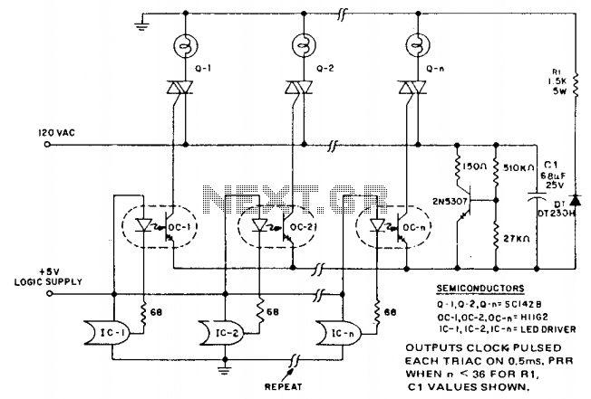
The described circuit functions as an efficient control mechanism for multiple loads, particularly in applications where cost and space are critical factors. The use of a microprocessor allows for sophisticated control algorithms, which can optimize the operation of the system while minimizing component costs. The incorporation of optocouplers enables electrical isolation between the control logic and the high-power loads, enhancing safety and reliability.
The Darlington output optocoupler serves a dual purpose; it not only provides the necessary gate current pulses to trigger the triacs but also simplifies the circuit design by eliminating the need for additional components like current limiting resistors. This design choice is particularly advantageous in high-density applications where space is at a premium.
The shared resistor and capacitor configuration allows multiple Darlington-triac pairs to operate efficiently, leveraging the low duty cycle of pulsing to reduce overall component size and cost. The timing of the IRED current pulses is tightly controlled by the logic clock, ensuring that the triacs are only activated when necessary, thus conserving energy and minimizing heat generation.
The absence of a current limiting resistor is a critical design feature that enhances the switching performance of the H11G2 optocoupler. By avoiding the Miller effect, the circuit maintains fast switching speeds, which is essential for reliable triac operation. The careful selection of components, such as the dipped tantalum capacitor, further contributes to the circuit's efficiency and effectiveness in high-power applications.
Overall, this circuit design exemplifies a cost-effective and efficient approach to controlling multiple loads in microprocessor-based systems, particularly suitable for large-scale displays and similar applications.In microprocessor control of multiple loads, the minimum cost per load is critical. A typical application example is a large display involving driving arrays of incandescent lamps. This circuit provides minimal component cost per stage and optocoupler triggering of triac power switches from logic outputs. The minimal component cost is attained by using more complex software in the logic. A darlington output optocoupler provides gate current pulses to the triac, with cost advantages gained from eliminating the current limiting resistor and from the low cost coupler.
The trigger current source is a dipped tantalum capacitor, charged from the line via a series resistor with coarse voltage regulation being provided by the darlington signal transistor. The resistor andxapacitor are shared by all the darlington-triac pairs and are small in size and cost due to the low duty cycle of pulsing. Coupler IRED current pulses are supplied for the duration of one logic clock pulse (2-10 /isec), at 0.4 to 1 msec intervals, from a LED driver I.C.
The pulse timing is derived from the clock waveform when the logic system requires triac conduction. A current limiting resistor is not used, which prevents Miller effect slowdown of the H11G2 switching speed to the extent the triac is supplied insufficient current to trigger. Optodarlington power dissipation is controlled by the low duty cycle and the capacitor supply characteristics.
🔗 External reference
Related Circuits
A newly licensed individual is engaging in traditional methods of amateur radio, focusing on continuous wave (CW) communication and homebrewing. They have constructed several basic receivers, an antenna matcher, a standing wave ratio (SWR) meter, a PC-rig interface, and...
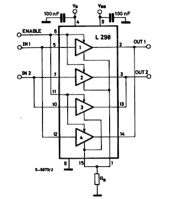
The L298 IC H-Bridge DC motor driver features two H-Bridge circuits, allowing it to control two DC motors simultaneously. Each H-Bridge can deliver currents up to 2A, but when used in parallel, the L298 can provide a total current...
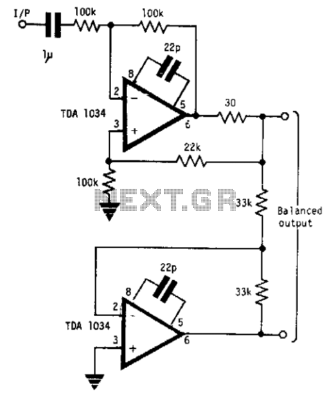
This circuit will handle +24 dBm with ± 12 volts supply using TDA 1034s. This circuit uses current and voltage feedback. The described circuit utilizes the TDA 1034S integrated circuit, which is designed for audio applications and can handle an...
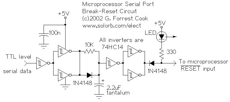
This circuit enables a remote microprocessor to reset the control of a host by sending an interrupt signal over an RS-232 or RS-422 serial line. When the remote machine is restarted using a simple program loader, it may cause...
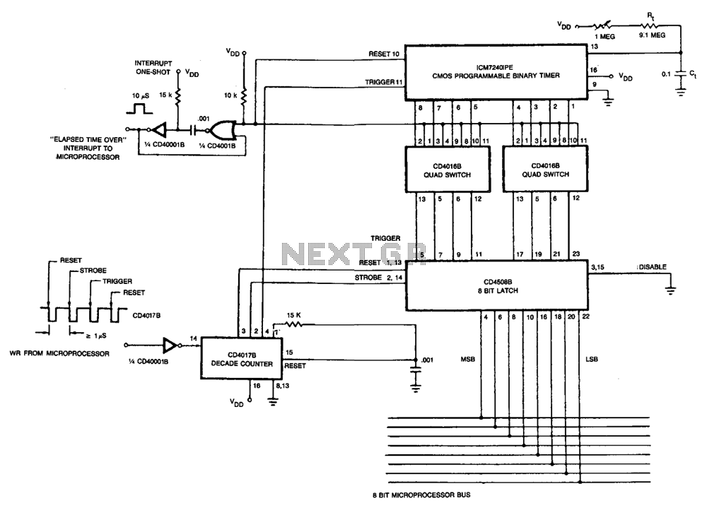
The microprocessor transmits an 8-bit binary code through its 8-bit I/O bus, which is necessary for programming the ICM7240. This is followed by four WRITE pulses directed to the CD4017B decade counter. The first pulse resets the 8-bit latch,...
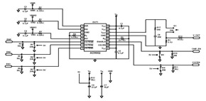
This schematic was created using a 2-layer evaluation board for the AD9662 3-Channel Laser Diode Driver. This device is primarily utilized in high-performance CD-DVD recordable drives and for laser diode current switching. The AD9662 is a specialized integrated circuit designed...