
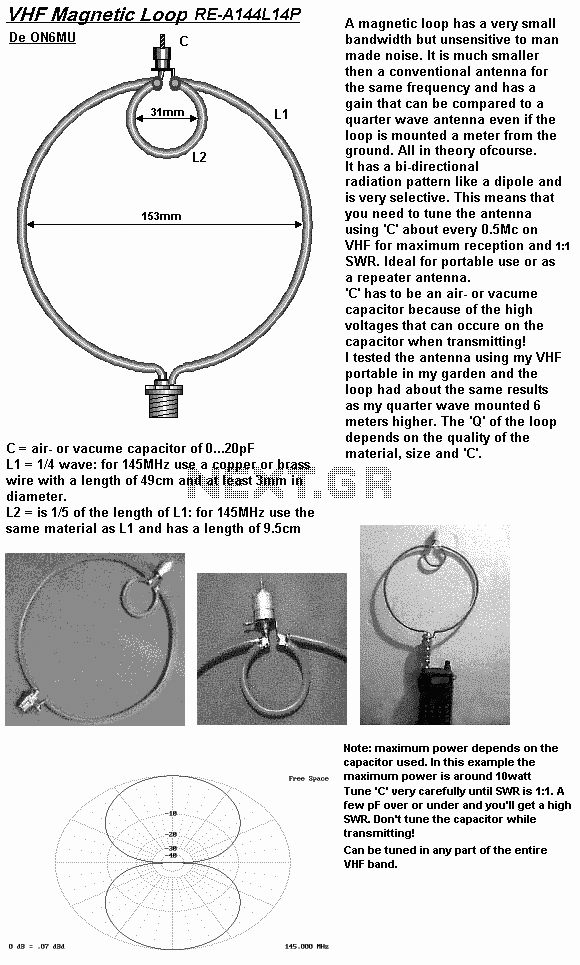
Mag Loop

The described system is a sophisticated automatic tuning mechanism for magnetic loop antennas, designed to mitigate the risk of damage due to high SWR conditions. The implementation of a microprocessor-driven controller enhances the tuning process by allowing for precise adjustments in real-time, based on feedback from an SWR bridge. The transition from a conventional analog motor to a stepper motor represents a significant advancement in tuning accuracy, enabling the system to effectively hone in on resonance without overshooting.
The use of a butterfly capacitor is particularly advantageous due to its continuous rotation capability, which facilitates fine-tuning adjustments. The controller's ability to monitor SWR and adjust motor direction accordingly is a critical feature that ensures optimal performance. The integration of limit switches for vacuum variable capacitors is an innovative solution to guide the controller's actions, enhancing the system's versatility.
The choice of the Motorola MC68HC908QY4 microprocessor is noteworthy, as it provides sufficient processing power for the control algorithms while minimizing additional component requirements. The half-step mode operation of the unipolar stepper motor allows for smoother transitions and more granular control over the tuning process, which is essential for achieving the desired resonance in varying conditions.
Overall, this system exemplifies the integration of modern electronics and automation in the field of amateur radio, providing users with an effective tool for managing the complexities of magnetic loop antenna tuning. The ongoing development of additional features, such as a remote phase detector, indicates a commitment to continuous improvement and innovation in antenna technology.Electronic equipment is not `cheap` and can be damaged in a number of ways, by electro-static discharge, by lightning and by transmitting withno antenna attached, or into an antenna with a high SWR. The controller described herein attempts to facilitate the safe and automatic tuning of a mag loop antenna by reducing the output power to an acceptable level via ALC control so the RF output
circuitry will not be damaged when the line SWR is high For several years now I have been experimenting with Magnetic Loop Antennasat this QTH. In the beginning, I tried octagonal 3/4" copper loops with homebrew trombone` capacitors wrapped in Teflon tape and driven by a surplus screwdriver motor.
While they worked OK, they were a real nuisance to peak after QSY`ing. After this, I built a similar loop that used an MFJ butterfly capacitor, driven by the very same motor that MFJ uses in their magloops. The motor was controlled by a microprocessor and an SWR bridge designed to automatically sense resonance.
This semi-automated approach worked better, but experienced difficulty hitting the sweet spot` as the analog motor controlled by a M/P generated PWM signal would often drift past resonance, and the controller would keep hunting back and forth over it. Operation was not always consistent. Finally, at the suggestion of Byron WA8LCZ I used a stepper motor in conjunction with the MFJ butterfly capacitor and programmed the controller to automatically hunt for resonance.
The microprocessor driven controller when activated will perform the following steps: If desired, the capacitor can be rotated manually, at either slow or fast speed. Resonance will be noted by themarked increase in background noise. The current design works best with butterfly capacitors as it`s very difficult for the controller to determine in which direction to rotate the capacitor unless the detected SWR happens to fall within the capture range of the Directional Coupler (described later).
If the SWR is 4:1 or less, then the controller will move the stepper in one direction while noting any increase or decrease in SWR, adjusting accordingly. However, if the SWR is higher, then the controller will keep moving in the initial direction while watching` for a decrease in SWR.
Once found, it will zero in`. With a butterfly capacitor (rotatable over360 degrees), this is no problem. I`m still trying to develop an efficient remote phase detector to tell` the controller in which direction to move the capacitor. The best I can offer for thosewishing to use a vacuum variable, for example, is a limit switch` type of sensor at the capacitor itself which, when activated, will alert the controller to change direction.
The stepper motor design is more complex than conventional analog motors (as used in the MFJ Magnetic Loop design and in homebrew loops) where the end of tuning travel interrupts the current feeding the motor via the limit switch. This current interruption` followed by a polarity reversal willnot work with a stepper motor as the controllerneeds to reverse the stepping sequence.
This website will not go into any exhaustive details about how to build magnetic loop antennas as there are many excellent sites written by authors much more experienced than me. For anyone who is interested, however, I will briefly describe the magnetic loop I`m currently using with the intelligent controller should anyone care to replicate this design.
The controller itself is driven by a Motorola MC68HC908QY4 flash programmable microprocessor (M/P). The controller has been programmed to move the UNIPOLAR stepper motor in either the forward or reverse directions using the half-step mode. The simplicity of this approach is that no additional stepper motor interface chips (aside from the 4 TIP-122`s needed to drive the motor itself) are required.
All the "stepping` code iswithin the M/P. However, one potential drawback is that the 🔗 External reference
Related Circuits
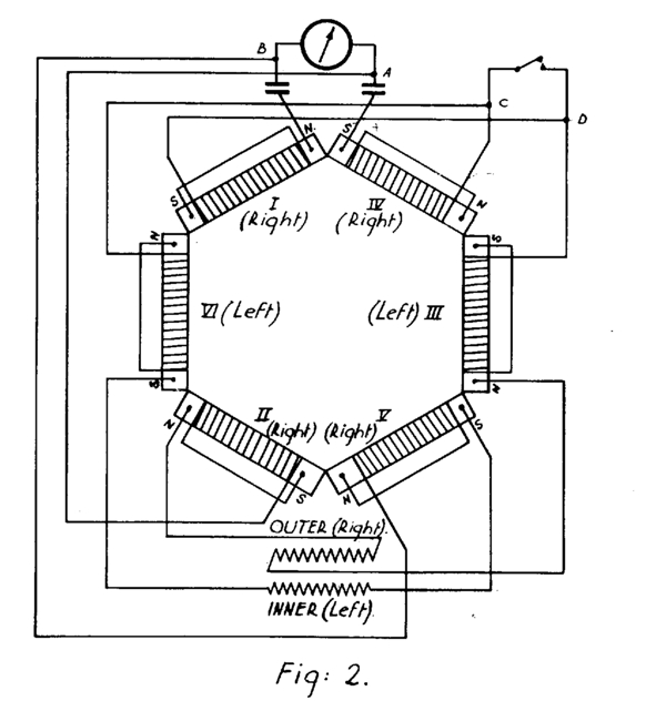
A potential source of quiet and limitless energy for submarine propulsion is described. This hexagonal configuration of coils and magnets, along with two "rotating" sub-circuits, operates without an external power source. Despite this, it seemingly generates or transduces power...
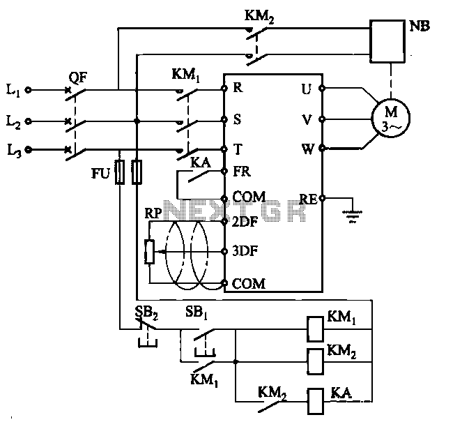
Electromagnetic brake motors consist of a motor and an electromagnetic brake, forming a standard assembly. The circuit diagram is provided. In this configuration, FR represents the forward run and stop command terminal, while the intermediate relay KA is employed...
Most Bulle clocks require their magnets to be rejuvenated before they can operate correctly with a standard 1.5V cell. The first significant magnet material was cobalt-chrome steel, introduced in 1921. Prior to this, carbon steel was hardened through heating...
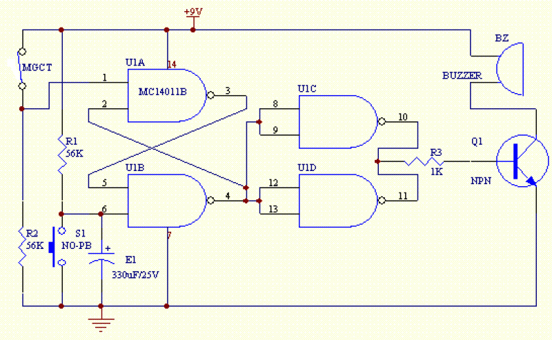
The circuit shown below is a basic latching circuit consisting of a quad 2-input NAND Gate IC. It is configured such that the flip flop circuit U1A and U1B has both its input held at logic "1". Pin 1...
A loop antenna is a radio antenna made up of a loop (or loops) of wire, tubing, or other electrical conductor with its ends connected to a balanced transmission line. This design includes two distinct types of antennas: the...
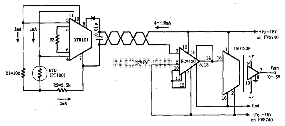
The circuit comprises an isolated RTD loop current configuration utilizing the XTR101 for transmitting loop current and the RCV420 for receiving it. The instrumentation amplifier detects changes in temperature via a resistance temperature detector (RTD), converting these changes into...