
Simple Magnetic Contact Alarm Project

The described circuit functions as a basic latching mechanism utilizing a quad 2-input NAND gate IC, specifically configured to operate as a bistable multivibrator or flip-flop. The circuit is composed of two primary NAND gates (U1A and U1B) that are interconnected to maintain their state based on the input conditions.
In the default state, both inputs of the flip-flop (U1A and U1B) are held high (logic "1"). This is achieved through the magnetic contact sensor connected to pin 1, which maintains a high state when closed, and a pull-up resistor (R1) connected to pin 6. The configuration ensures that the flip-flop remains in a stable state until a reset condition is triggered.
The reset mechanism is facilitated by a normally open push-button switch (S1). When S1 is pressed, it momentarily pulls pin 6 low (logic "0"), causing the output of U1B to transition to high (logic "1"). This change propagates through the circuit, resulting in the output at pin 4 of U1B becoming low (logic "0"). The subsequent inversion of this output by the additional NAND gates (U1C and U1D) produces a low signal at the base of the transistor (Q1), turning it off and silencing the connected buzzer.
Conversely, when the magnetic contact sensor opens, pin 1 transitions to low (logic "0"). This results in the output of U1A switching to high (logic "1"), which in turn makes the input of U1B high as well. The output of U1B then goes low (logic "0"), leading to a high output from U1D. This high signal activates the transistor Q1, allowing current to flow through the buzzer, which results in the buzzer sounding continuously until the reset button (S1) is pressed again.
Overall, this circuit effectively demonstrates a simple yet functional latching mechanism, allowing for an audible alert that can be reset by the user, making it suitable for applications such as security alarms or notification systems.The circuit shown below is a basic latching circuit consisting of a quad 2-input NAND Gate IC. It is configured such that the flip flop circuit U1A and U1B has both its input held at logic "1". Pin 1 is held at logic "1" by the magnetic contact and pin 6 is held at logic "1" by resistor R1. S1 switch is a normally open push-button switch which is used as a reset button. When S1 is pressed, the input pin 6 will be at logic "0", hence the output of U1B will go to logic "1". This logic is inverted by U1C and U1D to logic "0". The transistor Q1 will be OFF and buzzer will not sound.
When the magnetic contact sensor is opened, the input to pin 1 will be at logic "0", giving an output of logic "1" at pin 3 of U1A. Pin 5 of U1B will go "1" and pin 6 will be "1" as well giving an output at pin 4 a logic "0".
This will be inverted and a logic "1" will be generated at the base of transistor Q1. The transistor Q1 will turn ON and cause the buzzer to sound continuously until the reset switch S1 is pressed.
Related Circuits
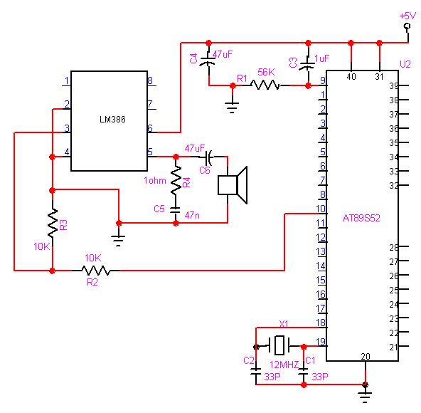
The 8051 microcontroller can play music tones. Here is a sample circuit and code that will play the music for "wishes you to be..." The 8051 microcontroller is a versatile and widely used microcontroller in embedded systems, capable of performing...
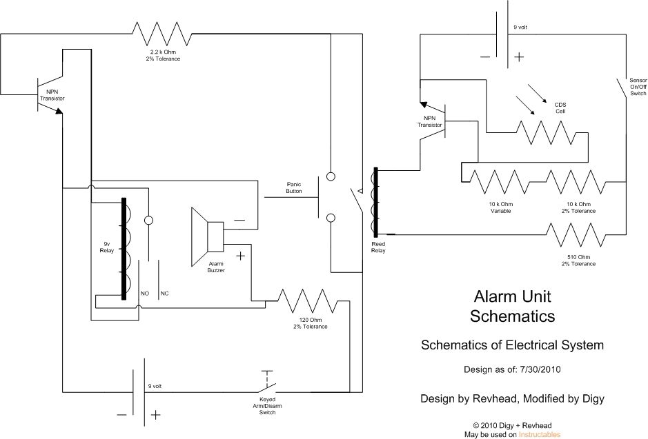
Learn how to strengthen your security system, regardless of its size, with this innovative and customizable laser grid. Once an individual crosses the threshold, the system activates... The concept of a customizable laser grid for security applications involves the deployment...

This audio mixer circuit diagram electronic project is designed using a few common electronic components. The audio mixer circuit project has two input channels. The input signal can be independently controlled using the R1 and R2 variable resistors. The...
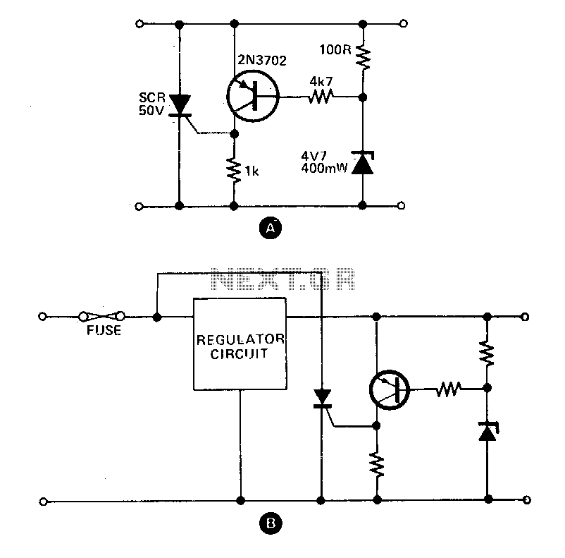
These circuits provide overvoltage protection in the event of a voltage regulator failure or the application of an external voltage. They are designed to be used with a power supply that includes some form of short circuit protection, such...
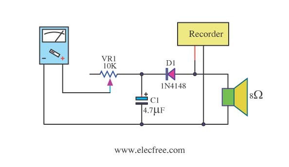
Expensive stereo systems generally feature VU meters that help indicate maximum power levels to prevent overloading. However, typical radio tape players do not include VU meters. A potential solution involves using a multimeter as a replacement. This can be...
A rain sensor alarm circuit is a useful device for alerting when rainfall occurs. The rain detector circuit presented is straightforward, utilizing only three components while maintaining high sensitivity to detect rain or moisture. The sensor can be constructed...
Warning: include(partials/cookie-banner.php): Failed to open stream: Permission denied in /var/www/html/nextgr/view-circuit.php on line 713
Warning: include(): Failed opening 'partials/cookie-banner.php' for inclusion (include_path='.:/usr/share/php') in /var/www/html/nextgr/view-circuit.php on line 713