
mains voltage detector

The circuit operates by utilizing an optocoupler to provide electrical isolation between the mains voltage and the control circuit. The design incorporates a bridge rectifier (B1) that converts the AC mains voltage to a DC voltage, allowing the LED in the optocoupler to function effectively. The potential divider formed by resistors R1 and R2, along with capacitor C1, ensures that the correct voltage and current levels are maintained for the LED to operate within its specified parameters.
When the appliance is switched on, the mains voltage is applied to the potential divider, allowing current to flow through the LED. The resulting illumination activates the photo-transistor within the optocoupler, enabling it to conduct and signal the downstream circuit. This feature is critical for applications requiring automatic detection and response to the appliance's operational status.
The circuit's design also emphasizes safety and reliability. The inclusion of fuse F1 serves as a protective measure, ensuring that the monitored appliance remains safeguarded from potential overloads or faults. The optocoupler's maximum switching voltage rating of 30 V further enhances the circuit's robustness, allowing it to handle varying operational conditions without failure.
In summary, this detector circuit is a versatile solution for monitoring appliance connectivity to mains voltage, with applications ranging from audio equipment integration to safety systems. Its efficient design and component selection make it suitable for a variety of electronic projects where reliable detection and signaling are required.The detector is intended to sense and signal to another circuit that an appliance is connected to the mains voltage. For this purpose, an optocoupler, IC1 in the circuit, is used. The light-emitting diode in this device is connected across the mains voltage rectified by bridge B1.
The mains voltage is applied to this bridge via potential divider R 1-C1-R2. When the capacitor has a value as specified in the diagram, the current through the diode is about 700 µA (for a mains voltage of 230 V). This results in sufficient light to make the photo-transistor conduct. The drop across the LED is about 1V. The detector draws a current only when the monitored equipment is switched on. It is intended to be built into the appliance whose mains connection is to be monitored and must, of course, be connected behind the mains on/off switch.
A possible application of the detector is in the preamplifier described in this blog (DIY: From vinyl to compact disc`). When it senses that the record player is being switched on, it can be used to link the Line-In input of the soundcard automatically to the preamplifier.
Another possible application is its use as a power-on reset circuit in a protection system. Transistor T1 can switch currents of up to 10mA; in the prototype, the knee voltage of the transistor was around 200mV at a current of 20mA. The maximum permissible switching voltage of the optocoupler is 30 V. Fuse F1 is added to allow a fuse to be omitted on the monitored appliance. 🔗 External reference
Related Circuits

The small DC voltages at the output of the diode detector are challenging to amplify accurately due to DC offsets introduced by any operational amplifier (op-amp) and low-frequency noise (1/f noise). A solution to these issues is to chop...
Whether it is truck throttling over the highway, an airplane soaring in the sky, a knock on the door, the purring of a cat, or simply your heartbeat, the vibration level detector circuit described here will sense them all...
The gas detector designed in this instance utilizes an ARM microprocessor as its core for measurement and control. It not only incorporates advanced one-chip computer microprocessing technology from the 1990s but also features several enhancements. The device employs an...
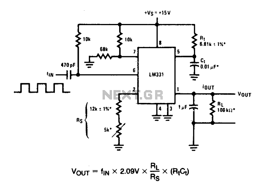
In these applications, a pulse input at a specified percentage is differentiated by a capacitor-resistor (C-R) network. The negative-going edge at pin 6 triggers the input comparator, activating the timer circuit. Similar to a voltage-to-frequency (V-to-F) converter, the average...
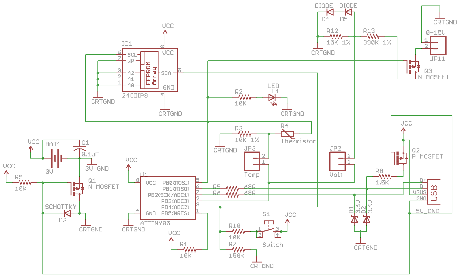
Combine the SATL and SAVL together. The schematic was updated with the voltage sensing circuit. A MOSFET was added to draw power from the voltage source only when needed. There are two jumpers, Temp and Volt, allowing the user...
It still uses a transistor to do some switching, and it still needs a pair of diodes and capacitors, as would be used in a conventional multiplier, but it doesn't require a steady stream of pulses and the output...