
Pulse Voltage Multiplier
There is no free lunch with this circuit. If the pulse is initiated before the 150k AND 100K resistors charge the 100 uf capacitor sufficiently (60k x 100 uf = 6 seconds), the output voltage will be lower than intended. The charge time of the circuit can be decreased by reducing the values of the capacitors, the output 100 uf capacitor having the most effect because of the high resistance charge path. Reducing the size of the capacitors will make the output pulse droop more quickly.
It should be noted that this circuit also makes a 0 to 10 volt pulse, which appears on the collector of the transistor. If a 0 to 10 volt pulse is desired, the circuitry to the right of the transistor's base resistor may be omitted.
This circuit functions as a voltage multiplier utilizing a switching transistor, diodes, and capacitors to achieve its output without requiring a continuous pulse stream. The transistor acts as a switch, controlled by the input signal, while the output voltage is determined by a resistor divider network composed of 100k and 150k resistors. This configuration allows for an additional 2 volts to be added to the 10-volt pulse present on the transistor's collector, resulting in a maximum output voltage of 12 volts.
In the design, the left-side diode can often be removed to simplify the circuit, with the 1k resistor being replaced by a 100k resistor. This modification, however, leads to a quicker voltage droop across the 100 µF capacitor, as it now discharges into both the 100k resistor and the load. The circuit's performance is contingent on the proper charging of the capacitors; specifically, if the pulse is applied before the resistors sufficiently charge the capacitor, the output voltage may not reach the desired level. The time constant for charging the capacitor is dictated by the product of the resistance and capacitance values (60k x 100 µF = 6 seconds).
To enhance performance, reducing the capacitance values can expedite the charging process, particularly for the output capacitor, which has the most significant impact due to its high resistance charging path. However, this will also lead to a more rapid droop of the output pulse voltage.
The circuit is capable of generating a 0 to 10-volt pulse at the collector of the transistor. For applications requiring this specific output, the components situated to the right of the transistor's base resistor may be excluded, streamlining the design further. Overall, this circuit is a practical solution for applications needing pulse voltage control without the need for continuous pulse input. It still uses a transistor to do some switching, and it still needs a pair of diodes and capacitors, as would be used in a conventional multiplier, but it doesn't require a steady stream of pulses and the output voltage is set by a resistor divider as the 100k and 150k resistors make 2 volts that are added to the 10 volt pulse on the transistors' collector. What it doesn't need is a steady stream of pulses to keep the output voltage pumped up all the time. The basic multiplier cell was inspired by a discussion I had with a well know laser scientist, Mr. Christoph Krah, about laser triggering circuits. After I finished this circuit, I sent it to Mr. Krah to get his opinion of how this circuit related to some of those we discussed years ago. For many of applications, the diode on the left side can be omitted and the 1k resistor changed to 100k.. This simplifies the circuit at the cost of slightly increasing the rate of droop of the voltage across the first 100 uf capacitor since it will discharge into the 100k resistor as well as driving the base resistor for the transistor and driving the load and 100k/150k voltage divider.
There is no free lunch with this circuit. If the pulse is initiated before the 150k AND 100K resistors charge the 100 uf capacitor sufficiently (60k x 100 uf = 6 seconds), the output voltage will be lower than intended. The charge time of the circuit can be decreased by reducing the values of the capacitors, the output 100 uf capacitor having the most effect because of the high resistance charge path.
Reducing the size of the capacitors will make the output pulse droop more quickly. It should be noted that this circuit also makes a 0 to 10 volt pulse, which appears on the collector of the transistor. If a 0 to 10 volt pulse is desired, the circuitry to the right of the transistor's base resistor may be omitted.
🔗 External reference
Related Circuits
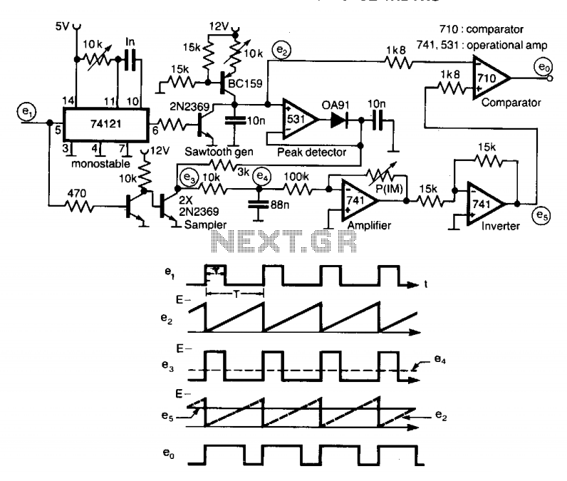
A circuit designed to multiply the width of incoming pulses by a factor that can be greater or less than unity is straightforward to construct. It features a single adjustable potentiometer for selecting the multiplying factor. This factor is...
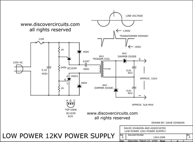
The 12kV High Voltage Generator utilizes a unique adjustment to generate approximately 12,000 volts with a current of about 5 µA. It consists of two SCRs forming two triggering circuit paths. These SCRs discharge a 0.047 µF, 400V capacitor...
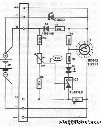
This voltage regulator for devices that utilize solar cells is straightforward and requires only a few electronic components. When a rechargeable energy storage device is employed, the voltage regulator circuit facilitates charging when the output voltage of the cell...
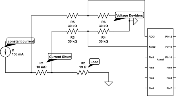
Measure current on a constant current source (LM317). Since a 3.3V chip is being used, a voltage divider is also required for reading the current. Will this circuit function correctly, or will it cause issues by attempting to increase...
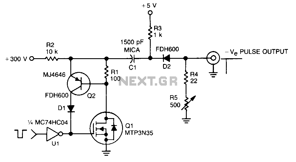
In this TMOS pulser, a negative-going pulse is applied to U1, a high-speed CMOS buffer, which directly drives the gate of Q1, an MTP3N35. If only a 100-V pulse is required, the MTA6N10 can be used. The pulse output...
This circuit accepts positive, negative, or differential control voltages. When the control voltage is zero, the output frequency is also zero. The described circuit functions as a versatile control voltage interface, capable of processing a range of input signals, including...